▲ Overview
The 3D Modelling feature allows you to display CAD models of certain robots.
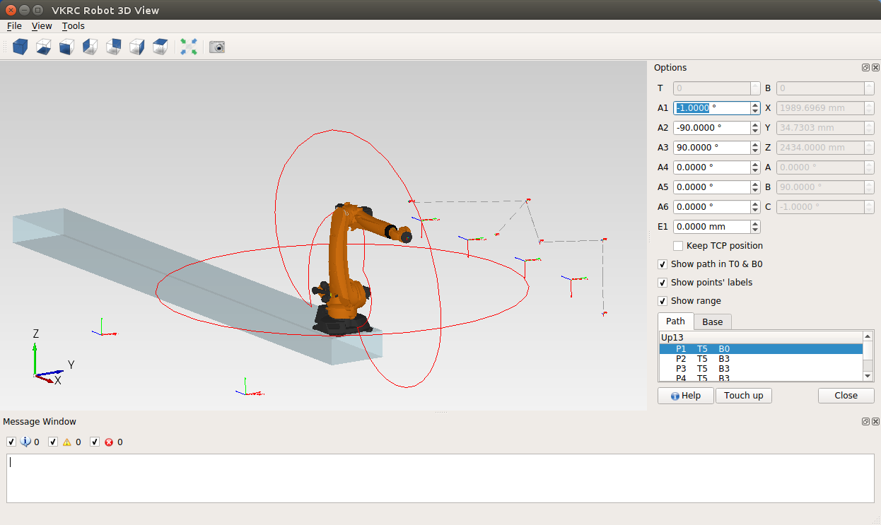
Every robot type has its own Robot 3D View (OLP) plugin which shows the path of the program opened in the editor in a 3D environment, lets the user move the robot, touch up points and add new points:
- KRC Robot 3D View
- VKRC Robot 3D View
- Fanuc Robot 3D View
- ABB Robot 3D View
- Yaskawa Robot 3D View (dummy model from the kinematics - no CAD models)
For some robots the working envelope can be displayed to check if the path points are on the reachability limit.
The user can move the robot and touch up the new point's coordinates (this feature is licensed).
▲ Settings
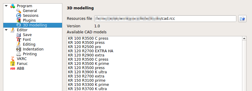
To display a robot model you need to download from our page the CAD repository.
If you don't find the given robot model please inform us and we will try to include it in the next update.
In the repository every link of a robot model (link0 – link6) is a STEP file (linkN.stp / linkN.step) or, since the CAD repository 3.2, a binary STL mesh (linkN.stl) for robots that are available only as meshes. STL links are shown in the 3D views of the editor and in the Robot Cell Simulator like STEP links (in the editor the base and the flange dark grey, the other links orange). The CAD repository 3.2 also contains the new model KR 270 R3100 K ultra (trafo KR270R3100K ULTRA C4 FLR).
▲ Continuous movement
▲ Robot model approximation
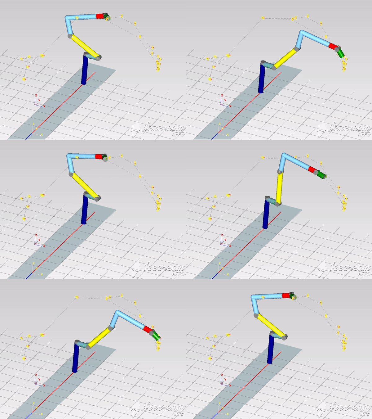
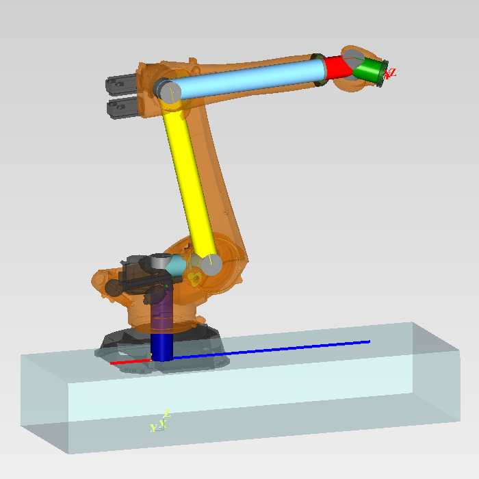
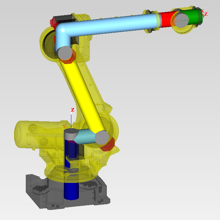
If the CAD model of the robot is not available the program can display a dummy model of the robot arm.
This model contains all kinematics parameters from the configuration file.
In the picture below you can see a comparison of the real CAD robot model and the dummy arm of Kuka and Fanuc robots.
In the picture below you can see a Fanuc robot on the rail moving through points.