▲ Overview
The plugin is available through DReS Menu → Tools → Plugins.
The user can open a *.psz file. This is an ordinary ZIP archive file which will be automatically extracted to the temporary directory.
The plugin will try to open StandaloneStudy_PsState.xml file with layout information.
You can extract this single file from the *.psz archive to avoid unnecessery temporary operation.
The user should set the Client System Root Path with the library of components through Menu → Tools → Set Client System Root first.
After loading StandaloneStudy_PsState.xml file a dialog box with all available 3D components will be shown.
The user can select those one that should be displayed.
If any preview image of the single component is available it will be shown.
Also approximate size of single JT file and total size of all selected components are displayed.
The user can navigate through context menu to select / unselect different items or ranges.
After loading all selected 3D components the user can select and display certain nodes through context menu of the model browser or 3D scene.
All devices are grouped into different device groups. This can be used to quick showing or hidding devices of certain group.
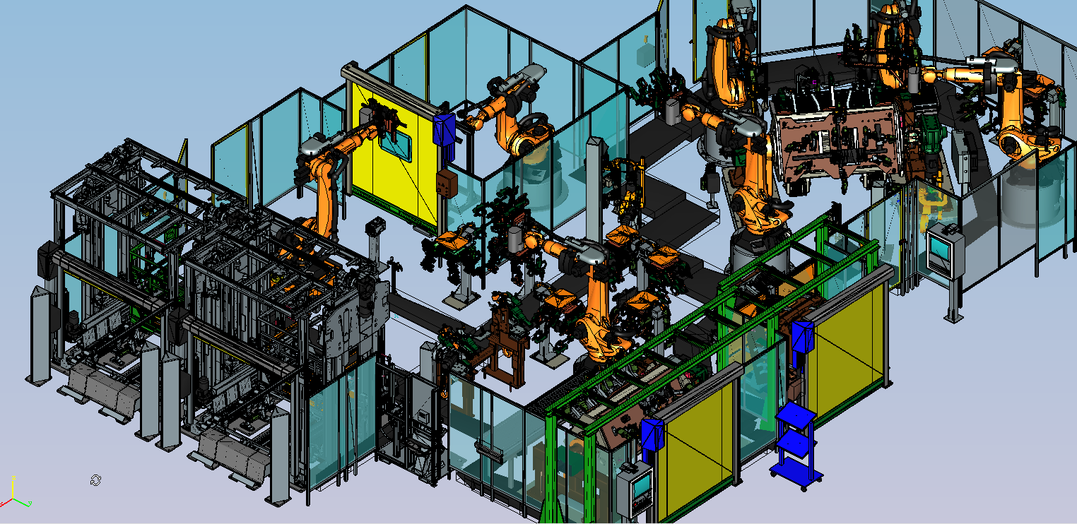
The user can change the scene backround to white through Menu → Tools → Draw White Background.
The user can attach / detach a tool to the robot and move it together with the robot axis through context menu options.
To move the robot axis suitable machine data should be placed in the directory containing robot JT model.
After selecting any robot root node in the model tree the tab Robot Axis will be enabled for moving the axis of selected robot.
Additional information can be found here.
▲ Moving robot
After selecting a robot item on model tree the current robot controller is set.
The user can move single robot axis and run available program.


▲ Simulation
The user can run selected robot program in single step or continuous mode and set robot motion speed.
The context menu of program list contains useful commands like:
- refreshing contents of Folgen and UPs directories
- reloading selected file
- opening selected file in DReS editor
- adding / removing breakpoints to the program
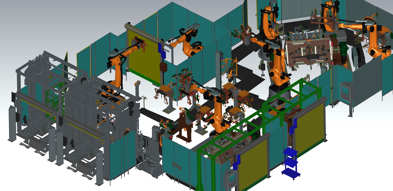
Below you can see sample path run.
The context menu of model tree has option to run given program for all robots.
▲ GPU
The plugin requires an extra dedicated graphics card to be able to display huge number of 3D components.
The GPU needs some extra adjustment to work in appropriate way, too.
Below you can find an example settings for Nvidia Quadro P600 with 4GB memory used for testing the plugin.
The test was performed on Dell Precision 3530 with i7 2.20 GHz, 16 GB RAM.
Select Use the advanced 3D image settings.

In the Global Settings select the following options.

Now select custom Program Settings for DReS editor to use.

▲ Limitations
During working with large 3D data the program can overload CPU or memory.
In case application crashes adjust your GPU settings or change dedicated buffer size in the plugin settings.
Please go to plugin Menu → Tools → Set Part Aggregator Size and enlarge the buffer size.
We were able to display around 1 GB of 3D components, around 65 000 parts.
The number of displayed parts is displayed in the OSD Statistics subwindow on the scene.
Our plugin can display up to 100 000 individual parts.
Current supported JT version is 9.5.