
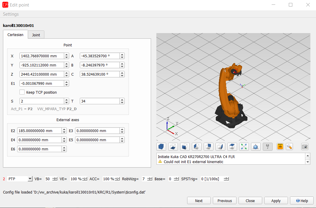
The upper part shows the Cartesian coordinates of the point (X, Y, Z, A, B, C, E1, S and T) and the external axes E2..E6; the Joint tab shows the same point as axis angles. The line below the fields says which variables of the .dat file hold the point (e.g. Act_P1 = P2, VW_MPARA_TYP P2_D). The bar below contains the motion parameters of the fold (motion type, VB, VE, ACC, RobWzg, Base, SPSTrig). Next / Previous step to the neighbouring motion, Apply writes the changes into the program, Close closes the editor without changing anything.
If the robot config file $config.dat was successfully loaded by cell.src selecting or manually the appropriate message will be displayed at the bottom left. If in the current config file there are any external axes configured and available, suitable parameter boxes become editable and give the user the possibility to change the position for this axis.
Be sure to load the correct $config.dat file before any changes.
If the $config.dat file was loaded successfully and there is an available CAD model a 3D robot model is shown.
You can move each joint separately in the defined robot working envelope.
See 3D Modelling for more information about this feature (the right part of the editor in the figure above).
If the robot CAD model is not available the editor will display a dummy robot shape.
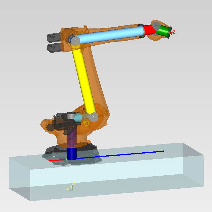
The external linear unit is shown as a cuboid under the robot base.
The cuboid geometry has the same length as axis limits of the robot and height equal to the mount position of the robot base.
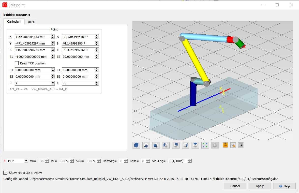
This shape corresponds to the real robot geometry.
For CIR and KCIR points the user can set start (auxiliary) and end point coordinates.
For LIN SUCHEN point the user can set all required parameters for linear searching movement as well.
Point's coordinates table
Below the program editor of an UP or a Folge there is a table with all points declared in the .dat file of the program: number, E6POS name, S, T, Tool, Base, X, Y, Z, A, B, C and the external axes E1..E6. The line above the table shows the axis values J1..J6 of the selected point, calculated with the inverse kinematics when the robot configuration is loaded.
- A double click on a coordinate cell opens a line editor for that value.
- A double click in the first column jumps to the motion that uses the point.
- A point selected in the program editor is highlighted in the table. For CIR and KCIR motions both points (auxiliary and end point) are selected.
- Changing Tool or Base of a point asks whether the coordinates should be recalculated, so that the TCP stays in the same place. No only changes the number (e.g. to correct a wrong tool number without moving the point).
Path tools. The context menu of the table has a submenu Path (TCP): path length of the selected points, estimated motion time, arc information, approximation and switch point checks and inserting a new point on the path at a given distance - see Path tools.
Unused points
A point declared in the .dat file that no motion of the program uses is shown in grey italics; the tooltip says why. Its values can still be edited in the table. A double click on it does not jump anywhere - there is no motion line - and the message Point not used in the program says so instead. The option Show only used points in the context menu hides such points.
Right-click menu of the point table
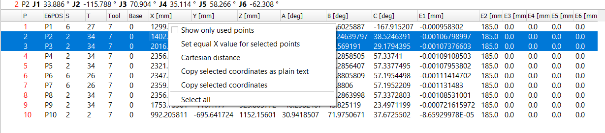
The entries depend on the clicked column, the number of selected rows and the content of the clipboard:
| Entry | When | What it does |
|---|---|---|
| Show only used points | always | Hides / shows points no motion of the program uses. |
| Set equal Tool / Base value for selected points | click on the Tool or Base column | Sets one Tool or Base number for all selected points. The question about recalculating the coordinates is asked once and can be applied to all of them. A summary lists updated, skipped and failed points. |
| Set equal <column> value for selected points | click on X..C or E1..E6 | Either sets a new value in that column for all selected points, or adds the entered value to their old values (Add to the old value). The last choice is remembered. Not offered for E1 when it is an external kinematic (ERSYS). |
| Switch E<n> value with another external axis | click on E1..E6 | Swaps the values of two external axes in all selected points. If the two axes are of a different type in $config.dat, a warning asks before the swap. |
| Copy P<n> coordinates | one row selected | Copies the E6POS of the point to the clipboard. |
| Cartesian distance | two rows selected | Shows the distance between the two points. |
| Copy selected coordinates as plain text | at least one row | Copies the selected rows with the header as tab separated text, e.g. for Excel. |
| Copy selected coordinates | more than one row | Copies all selected points to the clipboard, to be assigned to the same number of points in this or another program. |
| Assign coordinates to P<n> | one point in the clipboard | Overwrites the point under the cursor with the copied coordinates. |
| Assign coordinates to selected points | a list of points in the clipboard | Offered only when the number of copied points equals the number of selected rows; assigns them in order. |
| Select all | table not empty | Selects all rows. |
The name in Copy P<n> / Assign coordinates to P<n> is always the number of the point in the .dat file, i.e. the point the action really works on (not the number of the motion in the program).
Inserting a new motion point
Insert motion point (VKRC menu or the robot toolbar) adds a new motion at the cursor and opens the point editor on it.
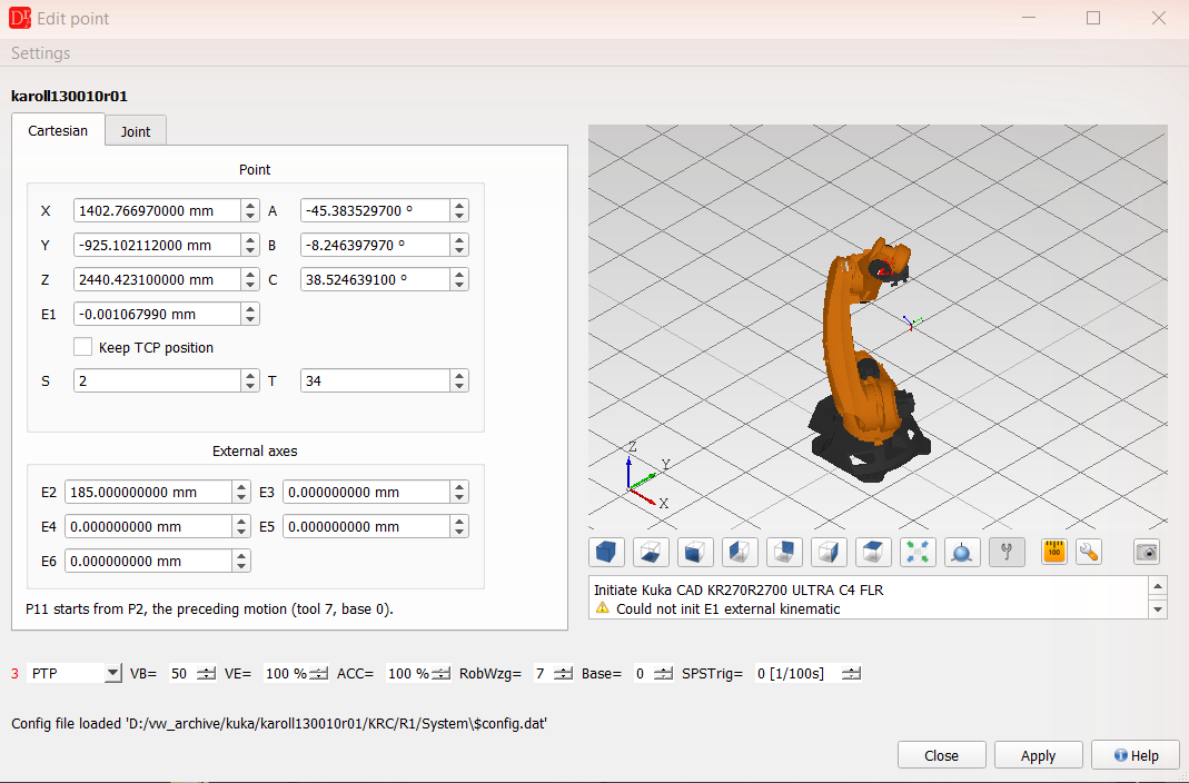
- The new point starts from the neighbouring motion - the preceding one, or the following one if there is none before the cursor: the coordinates (copied exactly as they are written in the .dat file), S, T, Tool and Base. The editor shows where the values come from, e.g. P12 starts from P11, the preceding motion (tool 7, base 0).
- If the neighbour has no S or T value, the insertion stops with the warning E6POS S value not defined / E6POS T value not defined.
- The new point gets the next free number (the highest used number + 1).
- The new motion is placed after the fold of the neighbouring motion, never inside it.
- Closing the editor without Apply removes the inserted motion again and restores the "modified" state of the program, so a point nobody confirmed does not stay in the program.