- Point table
- Editing values in the table
- IK / FK row and the list of IK solutions
- Unused points
- Context menu of the point table
- Point editor
- What Apply writes
- Inserting a new motion point
- Linear unit (E1)
- Tool and work object data
- Targets written directly in the motion instruction
▲ Point table
All robtarget and jointtarget variables declared in the current module are listed in two tables below the program text. Next to the coordinates the table shows the namespace (the fold or routine the declaration belongs to) and whether the variable is LOCAL, CONST or PERS.
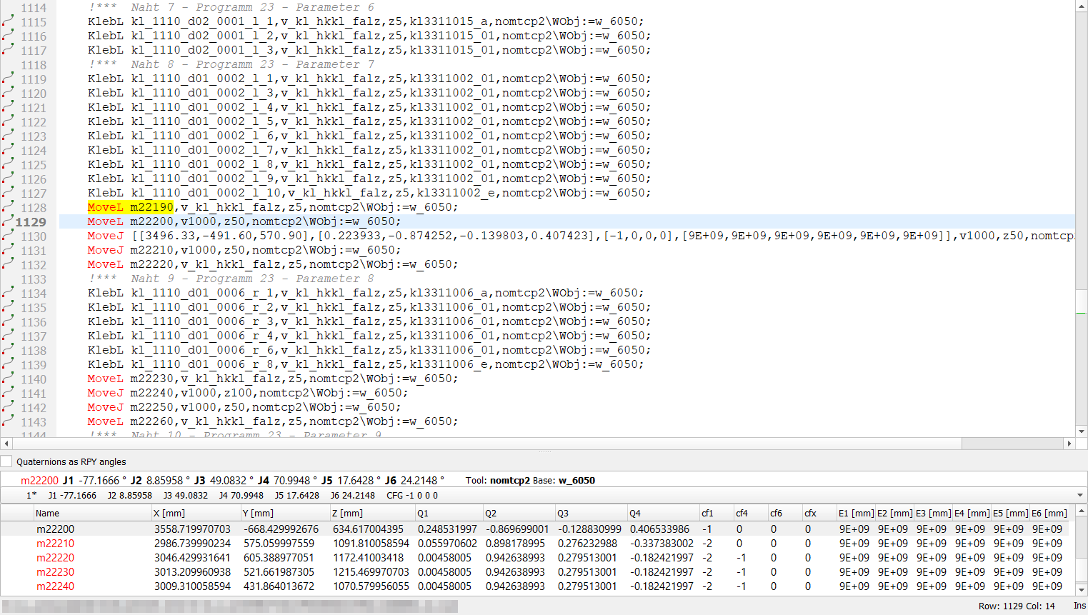
The table follows the cursor: placing the cursor on a point name in the program selects that point in the table. Double-click on a point name in the table jumps to its declaration.
Quaternions as RPY angles switches the orientation columns between the quaternion (q1..q4) and roll/pitch/yaw angles.
Numbers are shown with the precision set in the ABB settings, without trailing zeros; an external axis that is not connected is shown as 9E+09.
▲ Editing values in the table
Coordinates, orientation and external axes can be changed by double-clicking a cell. The configuration columns (cf1, cf4, cf6, cfx) are read-only - they are recalculated.
- Only the changed number is rewritten. The rest of the declaration - the other numbers in their original notation, spacing, the semicolon and a comment after it - stays exactly as it was, so a comparison of program versions shows only what was really changed.
- A quaternion component changes the whole orientation: after the edit the four components are normalized and written together. A quaternion of zeros is refused.
- A value that is not a number is refused, nothing is written.
- After a change of the coordinates the confdata is recalculated from the inverse kinematics, keeping the arm configuration the point was taught in (see below).
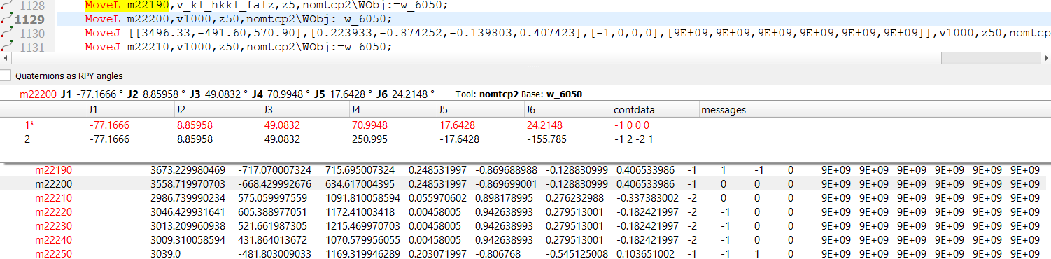
If the robot configuration of the project is available (system.xml, MOC.cfg and the robot kinematics), the row above the table shows the axis values of the selected robtarget (inverse kinematics) or the cartesian position of the selected jointtarget (forward kinematics), together with the tool and work object used by the motion instruction of that point.
The drop-down list under this row contains all IK solutions within the axis limits. The solution with the confdata of the point is marked with * and selected. Axes 4 and 6 may need a full turn (±360°) to reach the quadrant stored in the confdata - such a solution is added to the list as well, so the marked solution always matches the row above it.
Copy joints values in the context menu copies the axis values in degrees.
▲ Unused points
A point that nothing in the module uses is shown in grey italics with a warning icon; the tooltip explains why. A point counts as used wherever its name appears outside its own declaration, comments and strings - in a motion instruction, in Offs() or RelTool(), in an assignment or as a procedure argument.
Only LOCAL points are marked: a point without LOCAL can be used from another module of the task, so missing references in this module say nothing about it.
▲ Context menu of the point table
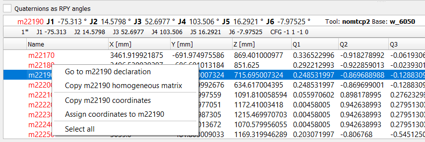
- Go to <name> declaration - jumps to the declaration in the program.
- Copy <name> homogeneous matrix / Copy <name> joints values - copies the position in the RoboDK format.
- Copy <name> coordinates - copies the whole declaration, e.g. robtarget p10:=[[...]];, taken from the program text, so the numbers keep their notation. The copied text can also be pasted directly into a program.
- Assign coordinates to <name> - shown only if the clipboard holds
coordinates of the same kind (robtarget to robtarget, jointtarget to jointtarget). Only
the value of the declaration is replaced - the prefix
(LOCAL CONST robtarget p10:=), the semicolon and a comment
stay as they were.
In RAPID a position only means something inside a particular \Tool and \WObj, and the values are assigned without any conversion. If the two points are used with a different tool or work object - or this cannot be established because one of them is not used in any motion instruction - the editor warns and asks before assigning. - Cartesian distance (two robtargets selected) - TCP distance, the |X|, |Y|, |Z|
differences and the angle between the two orientations. If the points use a different
tool or work object, the result is only a difference of raw coordinates and the window
says so.
Axes distance (two jointtargets selected) - the difference on every axis. - Select all.
The tool and work object data (tooldata,
wobjdata) are read from all modules of the task - system
modules (*.sys) and program modules (*.mod). They are needed for the kinematics and
for the tool/work object comparisons described above.
▲ Point editor
The point editor is opened by:
- Edit point from the context menu of the program text, on a line with a motion instruction or with a robtarget / jointtarget declaration,
- double-click on such a line.
Previous and Next move to the neighbouring points without closing the window.
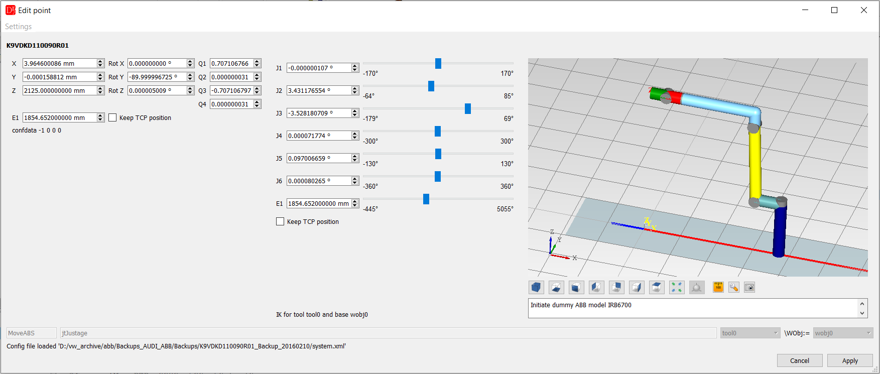
The Cartesian tab shows the position and orientation (quaternion and RPY angles) and the confdata, the Joint tab the axis values with sliders limited to the axis limits of the robot. A change on one tab recalculates the other one. The 3D preview shows the robot in the calculated pose.
▲ What Apply writes
- Only the numbers that were changed are replaced - the same rule as in the point table. A value typed in a field is written as typed (3506.33, not 3506.330078125), the quaternion is written as a group of four, and the rest of the line (the other numbers, the motion parameters, \WObj, the semicolon, a comment) stays unchanged.
- A declaration split over several lines is not rewritten - the editor reports it instead of breaking the declaration.
- confdata: the editor looks for the IK solution with the confdata of the point (including a full turn of axis 4 or 6), so the preview shows the arm configuration the point was taught in and Apply keeps the confdata. If no solution within the axis limits has this confdata, the editor says so, the preview shows the nearest configuration and Apply still keeps the confdata of the point. The configuration is changed only when you move the axes on the Joint tab.
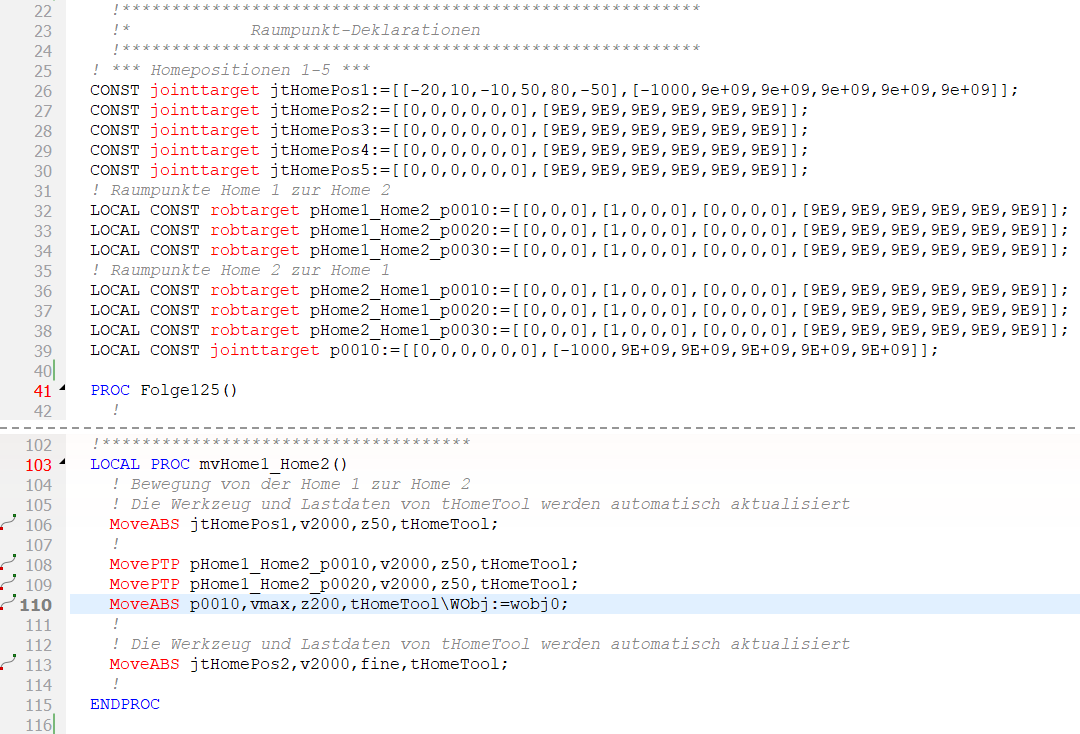
Insert motion point (robot toolbar, ABB menu or context menu of the program text) opens the editor for a new point. Nothing is inserted into the program before Apply - closing the window without it leaves the program unchanged.
- Choose whether the point is declared as robtarget or jointtarget. The choice is remembered for the next time.
- The new point starts from the neighbouring motion - the nearest motion instruction above the cursor, or below it if there is none above - together with its \Tool and \WObj. If the neighbour is stored in the other form, its position is converted (IK/FK). A robtarget copied from a robtarget keeps its confdata. The editor shows which motion the values come from. Switching between robtarget and jointtarget takes the values from the neighbour again, in the new form.
- The name is generated from the point name template (see Rename Point).
- Cursor inside a routine (PROC, FUNC, TRAP): the motion instruction goes to the line of the cursor, with the indentation of the neighbouring lines. The declaration (LOCAL CONST robtarget ...) goes to the module level - after the last point declaration before the first routine, or, if the module has none, right before the first routine and its header comment. A data declaration inside a routine body would be a syntax error.
- Cursor outside the routines: only the declaration is inserted, at the cursor. A motion instruction is not allowed there, the editor says so and leaves it out.
- The whole insertion is one Undo step.
▲ Linear unit (E1)
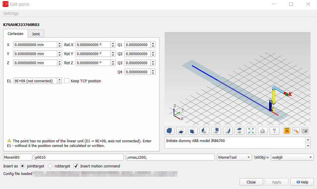
For a robot on a linear unit (track) the E1 fields and the slider are limited to the track limits read from MOC.cfg (section ARM of the track axis), in mm. The same limits are used to draw the track in the 3D preview.
The value 9E+09 means axis not connected. It is shown in the E1 field as 9E+09 (not connected) and written back as 9E+09.
- Robot without a linear unit: 9E+09 is the only correct value of E1, the E1 fields are hidden and nothing is reported.
- Robot with a linear unit: a point without the track position - or a new point whose neighbouring motion has none - cannot be calculated or written. The editor shows a message, the E1 field stays enabled and Apply waits until the track position is entered. Nothing is guessed.
▲ Tool and work object data
The kinematics needs the tool and work object data of the motion. If they cannot be found in the task, the other form of the point cannot be calculated and the 3D preview is not updated, but Apply is not blocked - what goes into the program does not depend on them:
- for a jointtarget the axis values from the Joint tab are written unchanged,
- for a robtarget the coordinates from the Cartesian tab and the confdata are written unchanged.
The editor also calculates IK and FK for points with an external TCP, but only if the tool and base configuration used in the motion is valid - tool data is NOT held by the robot and base data IS held by the robot.
▲ Targets written directly in the motion instruction
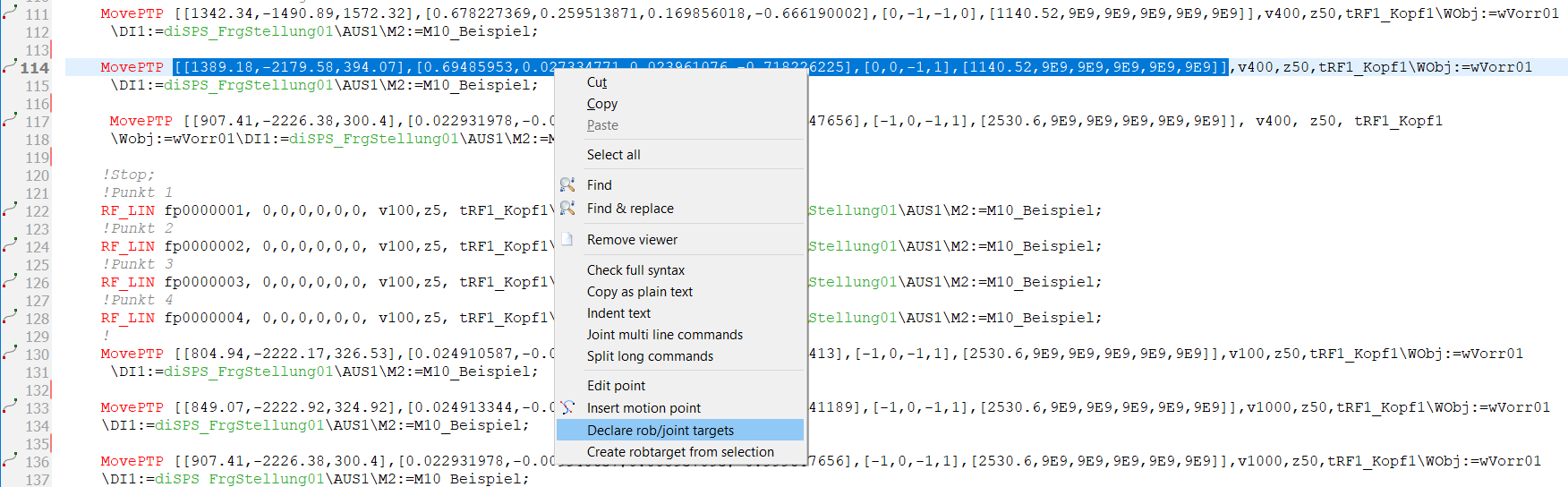
Some motion instructions carry the coordinates directly, e.g. MoveJ [[3496.33,-491.6,570.9],[...],[-1,0,0,0],[9E+09,...]],v1000,z50,tool1\WObj:=wobj1;
- Edit point on such a line edits these coordinates in place; Apply replaces only the changed numbers inside the brackets.
- Declare rob/joint target (context menu of the program text) declares a new LOCAL CONST variable with a unique name for every target written directly in the module and puts the name into the motion instruction. The rest of the instruction stays unchanged. The name template is set in the settings of the Rename Point plugin.