
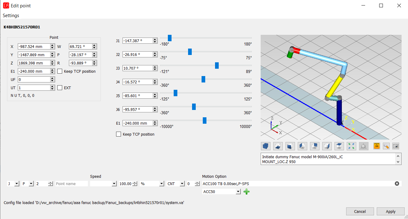
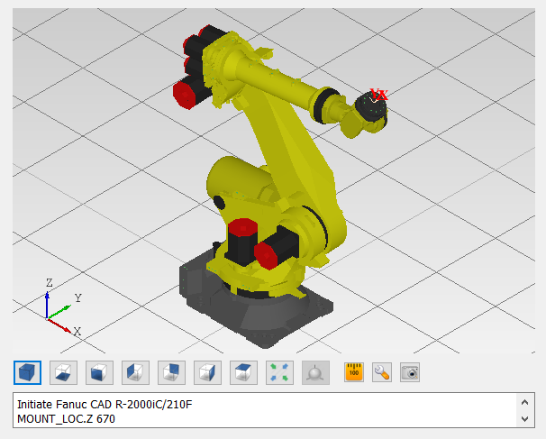
If the robot type was found in the CAD repository a real robot model will be displayed otherwise a dummy model will be shown.
See 3D Modelling for more information about this feature.
Point's coordinates table
In the figure below you can see a table with all points' coordinates in the single program.
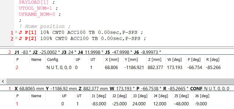
The user can edit certain values by double clicking on the cell.
After selecting a row, if the robot configuration file is available the inverse / forward position for the point is shown.
The context menu contains many additional features to help change the values.
The submenu Path (TCP) measures the path length and the motion time of the selected points, shows arc information, checks the approximation and the switch points (PS) and inserts a new point on the path at a given distance - see Path tools.
Unused points
A point declared in the /POS section that no motion of the program uses is shown in grey italics with a warning icon; the tooltip says why. Its values can still be edited in the table. A double click on it does not jump anywhere - there is no motion line - and the editor says so instead. Such a point cannot be copied or assigned from the context menu, because those functions work through the motion that uses the point.
UF and UT of JOINT points
For an XYZWPR point, changing UF or UT in the table asks whether the coordinates should be recalculated, so that the TCP stays in the same place. A JOINT point describes the angles of the axes and does not depend on the user frame or the tool, so for it only the UF / UT number itself is changed - nothing is recalculated.
Inserting a new motion point
Insert motion point (robot toolbar or VFanuc menu) adds a new motion after the line of the cursor and opens the point editor on it.
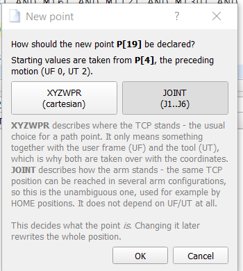
- First a window asks how the new point is declared: XYZWPR (position of the TCP in the user frame and tool) or JOINT (angles J1..J6). Only one of the two buttons can be active; the choice is remembered for the next time. The window also says where the starting values come from. Cancel inserts nothing.
- The new point starts from the neighbouring motion - the preceding one, or the following one if there is none before the cursor - together with its UF and UT, because XYZWPR coordinates mean something only in those frames. If the neighbour is stored in the other form, the values are converted (inverse / forward kinematics). If there is no neighbour, or the conversion fails, the point starts from zeros with UF 0 and UT 0, and the editor says so.
- The new point gets the next free number (the highest used number + 1).
- The new motion is never placed inside another motion. If the cursor is on a motion - also a collapsed one - the new motion goes after its last line, not between the header of that motion and its body.
- Closing the window without Apply removes the inserted motion again and restores the "modified" state of the document, so a point nobody confirmed does not stay in the program.