
The result is a warning, not a safety certification. The test uses the TCP of the taught points and the straight lines of linear motions (with an optional tool radius). The robot arm, the tool geometry, braking distances, zones that are switched by a signal and the real cell are not evaluated. The result does not replace the validation and the acceptance protocol of the safety configuration. The safety files of the controller are only read, never written.
Where: menu Plugins » Robot Safety View; command API:
plugin_cmd with the
commands safety_open, safety_calculate, safety_status, safety_zones,
safety_findings, safety_report, safety_image (see
VeRa / command API).
Examples
All examples show a robot named R1 and zones named "Zone n".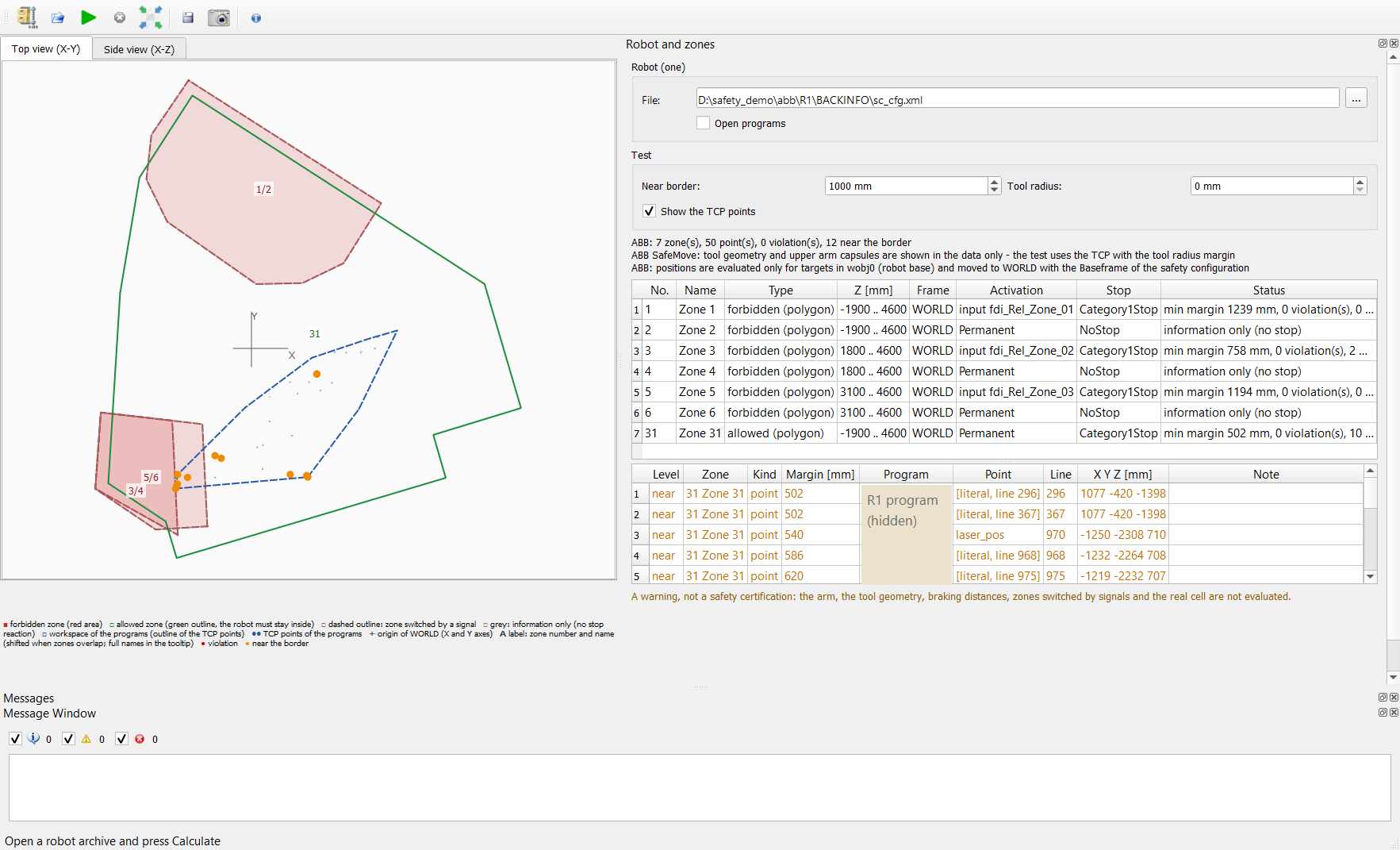
ABB SafeMove, top view: three forbidden zones (red, each with its occupancy supervision, labels 1/2, 3/4 and 5/6), the allowed work cell (green, label 31), the outline of the workspace of the programs (blue dashed) with the TCP points, and the points closer than 1000 mm to a border (orange; Near border = 1000 mm). 0 violations. The zone table shows the activation (input signal or permanent), the stop reaction and the minimum margin of each zone.
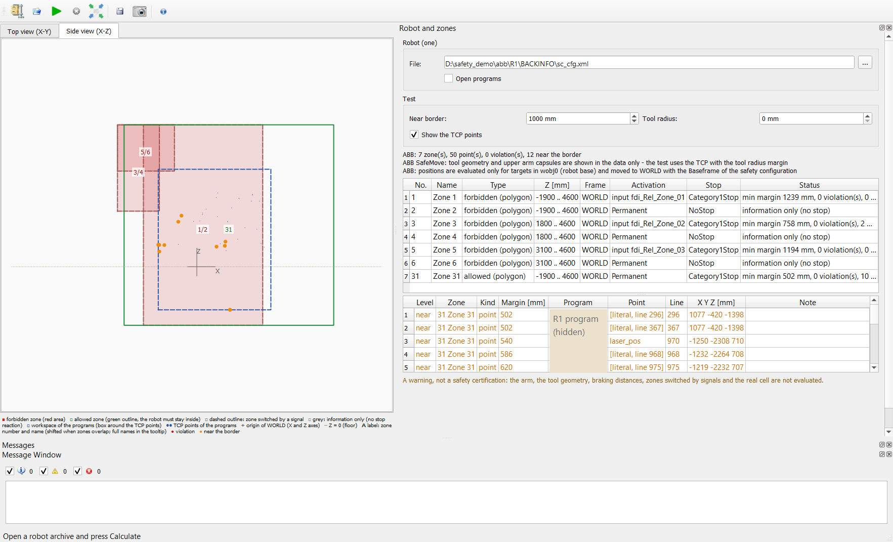
The same robot in the side view (X-Z): the zones with their Z limits, the box around the TCP points and the dotted line Z = 0.
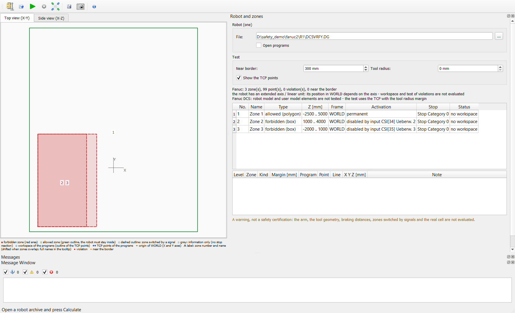
Fanuc DCS: the zones of the Cartesian Position Check (an allowed polygon, two forbidden boxes switched by a disabling input - dashed). This robot has an extended axis (J7), so the program does not guess its position in WORLD: the message in the panel says that the workspace and the test are not evaluated; the zones are still shown.
Example report: HTML and PDF - summary, zone table, findings and the images with the legend.
Reading the view
The images of this section come from two demo archives (a KUKA iiQKA robot with demo workspaces and a KUKA VKRC robot with circular motions). The demo zones were written into a copy of the archive to show every kind of marker; they are not the zones of a real cell.The result is a warning, not a safety certification. A finding means "look at this point in the program"; no finding does not mean that the cell is safe (the arm, the tool geometry, braking distances and the real cell are not evaluated).
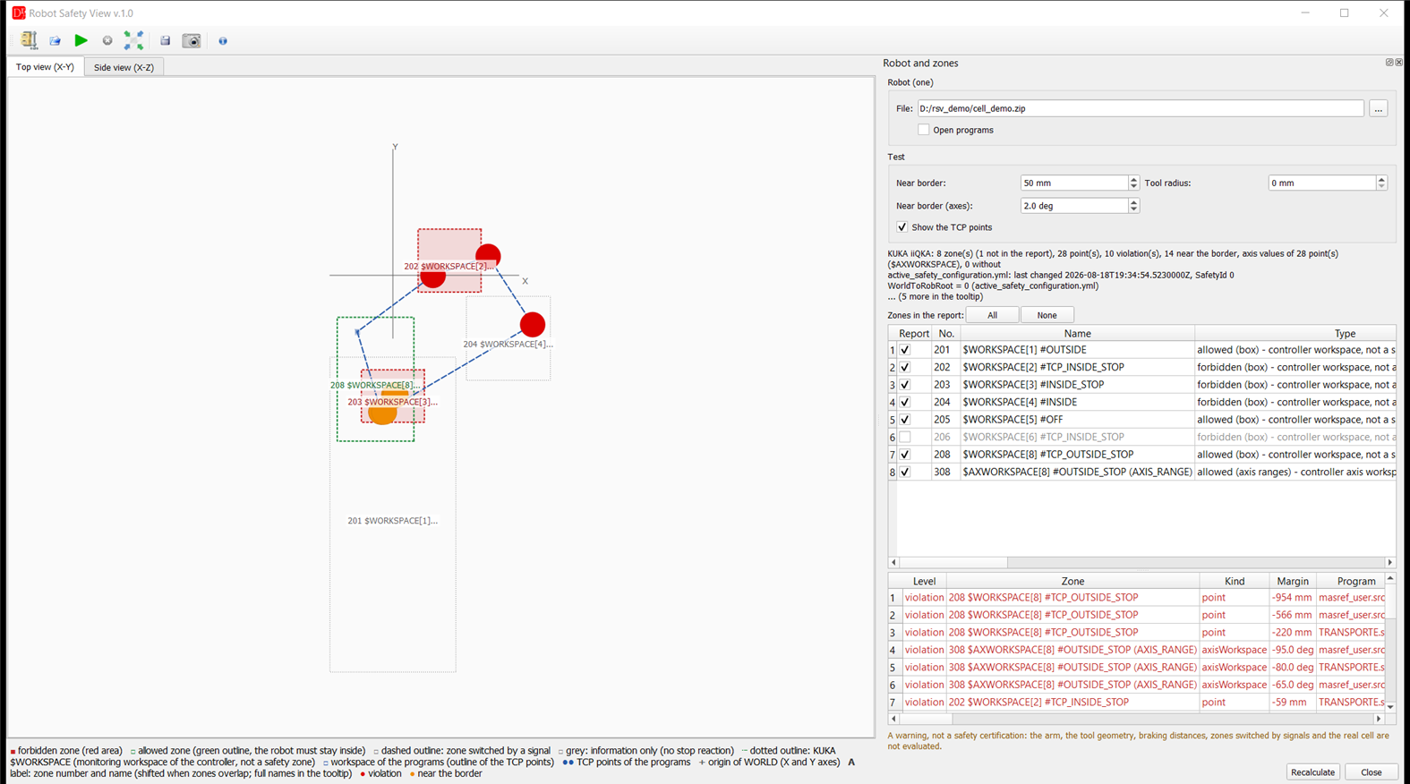
The window: on the left the drawing (tabs Top view (X-Y) and Side view (X-Z)) with the legend below it, on the right the panel Robot and zones with the file, the test settings, the summary, the zone table and the findings table. Demo: KUKA iiQKA, workspaces
$WORKSPACE[1..8] of $custom.dat and one axis workspace
$AXWORKSPACE[8]; Near border = 50 mm, Tool radius = 0 mm; zone 206 is excluded from the report.
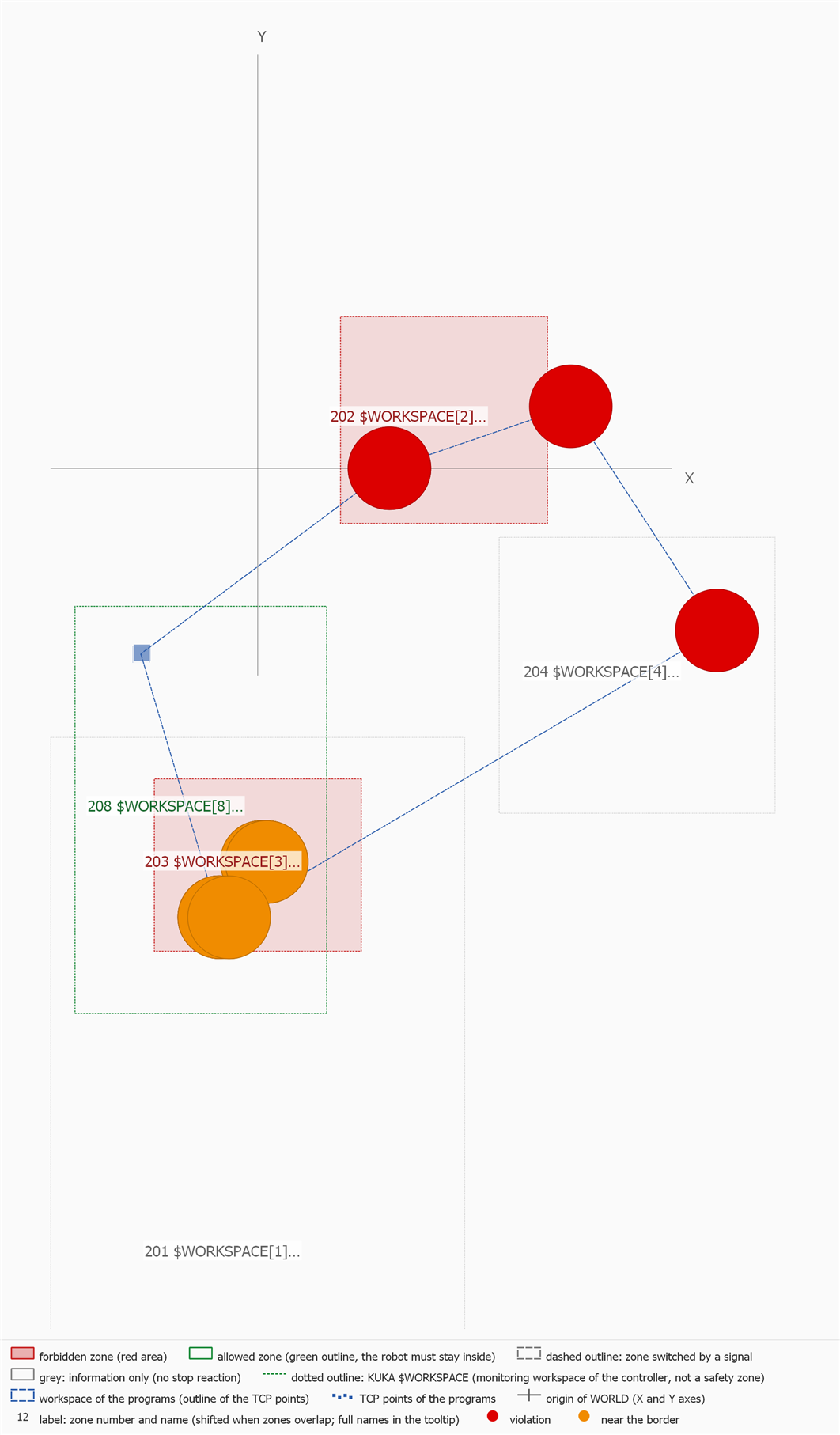
The same top view as an exported image (Export image... / API
safety_image), with the legend (the
lower part of the large grey zone 201 is cut off here). What it shows:
- 202
#TCP_INSIDE_STOP- forbidden zone (red area, dotted because it is a KUKA$WORKSPACE): a taught point lies inside - red dot, finding of the kind point, margin -59 mm. - 203
#INSIDE_STOP- a thin forbidden slab (Z 170 .. 200 mm). The end points of a linear motion lie above and below it, the straight line between them crosses it: finding of the kind segment, margin -15 mm. The two end points themselves are only near the border (orange) - in the top view their orange dots lie on top of the red dot of the segment. - 204
#INSIDE- a MODE without STOP only sets the outputSTATE: grey outline, information only, not tested. The red dot inside it is a finding of zone 208 (that point is outside the allowed zone 208), not of 204. - 201
#OUTSIDE- also information only (grey). - 208
#TCP_OUTSIDE_STOP- allowed zone (green dotted outline, no fill): the points outside it are violations (red), the points closer than 50 mm to its border on the inside are near the border (orange). - 205
#OFFis listed in the zone table ("disabled in the controller") and not drawn; 206 has no check mark Report: grey row, not drawn, not evaluated. - 308
$AXWORKSPACE[8]- axis ranges have no X-Y-Z shape: only in the tables, findings of the kind axisWorkspace with the margin in degrees. - The blue dashed polygon is the outline of the workspace of the programs (convex hull of all TCP points and arc points). Its edges are not robot paths.
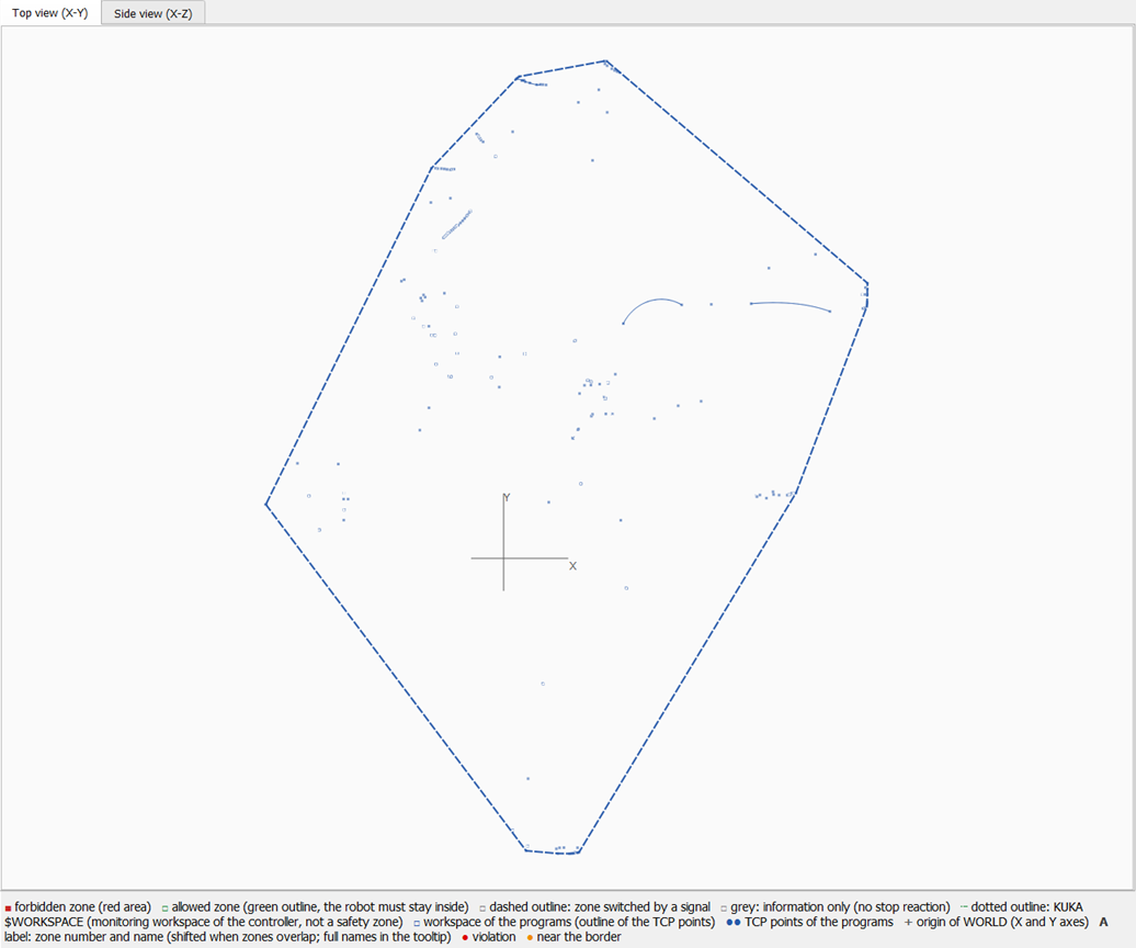
A robot with circular motions (KUKA VKRC, top view): the blue squares are the TCP points, the thin solid blue curves are circular motions (from the previous point through the auxiliary point to the target point), the blue dashed polygon is the outline of the workspace. The SafeOperation of this robot is switched off - its zone is listed as disabled and not drawn, so there is no finding.
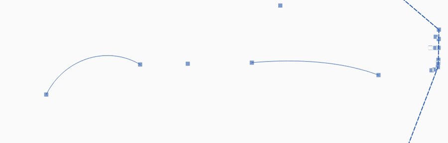
Detail of the exported top view: two circular motions drawn as arcs between their start and target points.
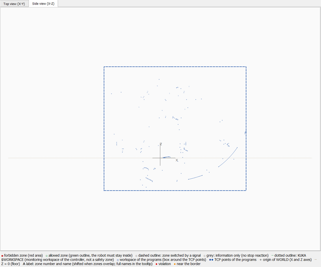
The same robot in the side view (X-Z): the box around the TCP points (blue dashed), the arcs, the origin of WORLD with the letters X and Z and the dotted line Z = 0.
Markers of the drawing
| Marker | Meaning |
|---|---|
| light red area with a red outline (2 px) | forbidden zone with a stop reaction: the TCP must not enter it. A violation is a point or a path inside it. |
| green outline (2 px), no fill | allowed zone with a stop reaction: the robot must stay inside. A violation is a point or a path outside it. |
| dashed outline (red or green) | zone switched by a signal (SafeOperation: activation by an input; Fanuc: disabling input; ABB: activation signal). It is tested as if it were active; the findings get the note "zone switched by a signal". Example: the Fanuc image in Examples above. |
| grey outline (1 px), no fill | information only: no stop reaction (KUKA MODE without STOP, ABB
NoStop, occupancy signals). Drawn, not tested, no findings. |
| dotted outline (red, green or grey) | KUKA $WORKSPACE[n]: a monitoring workspace of the controller,
not a safety zone. The colour follows the MODE (INSIDE_STOP = red, OUTSIDE_STOP = green, without STOP = grey). |
| not drawn | KUKA $AXWORKSPACE[n] (axis ranges, no X-Y-Z shape), zones switched off in the controller
(e.g. #OFF, SafeOperation switched off), zones with an error (e.g. tilted frame), zones without the check
mark Report. They are listed in the zone table. |
| blue dashed outline | workspace of the programs: top view - the convex hull of all TCP points and arc points; side view - the box around them (X and Z). |
| small blue squares | TCP points of the programs (target points in WORLD), only with Show the TCP points. |
| linear motions | not drawn as lines - their straight lines are tested (finding of the kind segment), the drawing shows their end points. |
| thin solid blue curve | circular motion (e.g. KUKA CIRC, Yaskawa MOVC) drawn as an arc from the previous point through the auxiliary point to the target point; tested along the arc (kind arc). Only with Show the TCP points. |
| large red dot (120 mm) | violation: at the TCP point (kind point) or at the deepest point of the straight line or of the arc (kinds segment, arc). |
| large orange dot (120 mm) | near the border: on the allowed side, but the margin (with the tool radius) is smaller than Near border. The dots are drawn in the order of the findings table (worst first), so an orange dot can cover a red one at the same place. |
| cross with X and Y (top view) or X and Z (side view) | origin of WORLD (the lines go from -300 to +600 mm). |
| dotted brown line (side view) | Z = 0 (floor). |
| label 202 $WORKSPACE[2]... | zone number and a short name (cut to 14 characters); zones with the same shape share one label (numbers joined with /). The full names are in the tooltip of the label and in the zone table. Labels keep their size when zooming and are moved when they would cover each other. |
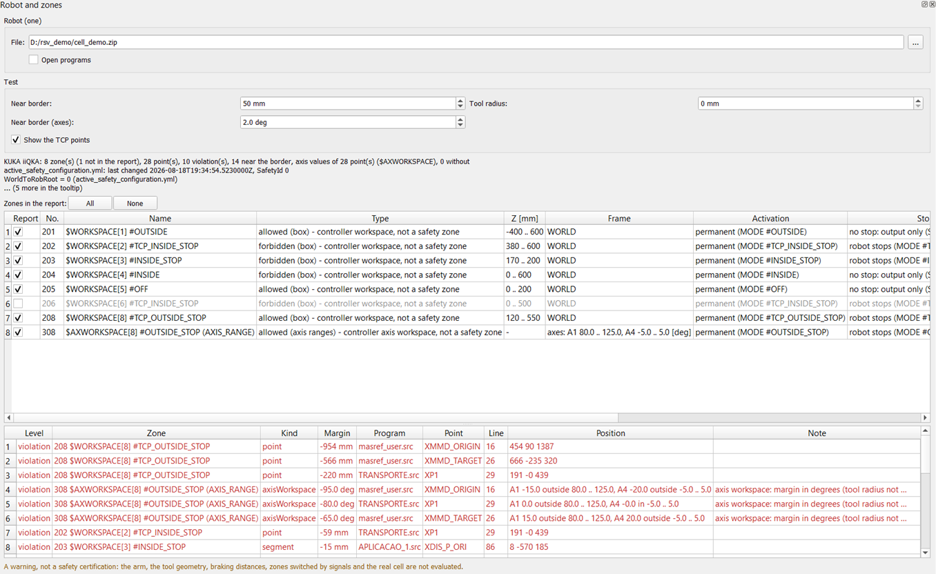
The panel Robot and zones of the demo (widened): the zone table with zone 206 excluded from the report (grey row) and the findings table with the kinds point, axisWorkspace and segment.
Zone table
| Column | Meaning |
|---|---|
| Report | check mark: the zone is evaluated, drawn and written to the report. Without the mark the row is grey and the zone is
not evaluated (status "not in the report (not evaluated)"). Buttons All / None; API
report_zones / report_exclude; remembered per archive. |
| No. | number of the zone: the number of the controller (Fanuc, ABB, SafeOperation spaces), 100 = cell area of
SafeOperation, 200 + n = KUKA $WORKSPACE[n], 300 + n = KUKA $AXWORKSPACE[n]. |
| Name | name from the safety configuration; KUKA: $WORKSPACE[n] <MODE>, $AXWORKSPACE[n] <MODE> (name). |
| Type | allowed or forbidden and the shape (box, polygon, axis ranges); for KUKA workspaces "controller workspace, not a safety zone". |
| Z [mm] | lower and upper Z limit (- for axis ranges). |
| Frame | coordinate system of the zone (WORLD, user frame ...); for $AXWORKSPACE the monitored axes and their ranges in degrees. |
| Activation | permanent, by a signal (dashed in the drawing) or the KUKA MODE. |
| Stop | reaction of the controller (robot stops / no stop: output only). |
| Status | result per zone: minimum margin, number of violations and of points near the border, or why the zone is not tested (information only, disabled in the controller, not in the report, error). |
Findings table (worst first, double click opens the program at the line)
| Column | Meaning |
|---|---|
| Level | violation (margin below 0) or near (margin from 0 to the value of
Near border, for $AXWORKSPACE Near border (axes)). |
| Zone | number and name of the zone. |
| Kind | point - the TCP of a taught point;
segment - the straight line of a linear motion from the previous point goes deeper into the zone than both of its end
points (the points themselves have their own findings);
arc - a circular motion, checked along the arc, goes deeper than its end points;
axisWorkspace - the axis values of a point against a KUKA $AXWORKSPACE (no position in the drawing). |
| Margin | distance to the border on the allowed side: in mm (the tool radius is subtracted), for axisWorkspace in deg. Negative = how deep the TCP or the path is on the wrong side. |
| Program, Point, Line | the program, the name of the target point of the motion and the line of the motion in the program. |
| Position | X Y Z in WORLD of the finding (for segment / arc the deepest point of the path); for
axisWorkspace the axis values against their ranges, e.g. A1 -15.0 outside 80.0 .. 125.0. |
| Note | e.g. "zone switched by a signal", "axis workspace: margin in degrees (tool radius not used)". |
Where the data come from (per robot)
| Robot | Programs (workspace) | Safety zones |
|---|---|---|
| Fanuc | text programs *.LS of the backup (the binary *.TP files are not read); TCP in WORLD from the
point data, UT / UF and the kinematics of the robot | DCSVRFY.DG |
| ABB | RAPID modules *.mod / *.sys (robtargets declared in the module or written in the instruction), tool and
work object from the instruction | BACKINFO\sc_cfg.xml |
| KUKA VKRC / KRC | Folgen, UPs and Makros *.src with the points of the .dat file
(TCP in WORLD, robot standing in WORLD only - see How Robot Safety View computes) | SCTLPARA.SAF (cell area and 16 monitored spaces) and the
workspaces $WORKSPACE[n] of KRC\STEU\Mada\$custom.dat and the axis workspaces
$AXWORKSPACE[n] of KRC\R1\Mada\$machine.dat (KUKA KRC only; both not shown for VKRC for now) |
| KUKA iiQKA | KRL programs *.src / *.dat of the backup (as KUKA KRC) | active_safety_configuration.yml,
the workspaces $WORKSPACE[n] of KRC\STEU\Mada\$custom.dat and the axis workspaces
$AXWORKSPACE[n] of KRC\R1\Mada\$machine.dat |
| Yaskawa | INFORM jobs *.JBI | FSU blocks //RBRNGLMT ... (detected, not interpreted) |
License
The basic license of the robot the report is about:VKRC_HASP (KUKA VKRC), KRC_HASP (KUKA KRC),
VFANUC_HASP (Fanuc), ABB_HASP (ABB) or YASKAWA_HASP (Yaskawa). The programs of a
robot without its basic license are not analyzed. The window opens without any license; the license is checked when you
press Recalculate or Read zones and it must be the one of the analyzed robot (an ABB archive needs the basic
ABB license, a VKRC archive the basic VKRC license, and so on), not any of them. A KUKA iiQKA archive (with the
safety configuration active_safety_configuration.yml or KRL programs of an iiQKA backup) needs the license
iiQKA instead of KRC_HASP. No additional license is needed.
How Robot Safety View computes
Robot Safety View compares points of the robot programs with the zones of the safety configuration. It is a plausibility check of the programs against the zones read from the archive - a warning, not a safety certification.1. Points: the TCP of every motion point in WORLD
- The programs of the robot (archive folder, open programs or files) are read in the background like for the other program checks; only motion instructions are used. For every motion the TCP of the target point is taken, with the tool of the point, and converted to WORLD. For a circular motion also its auxiliary point is converted to WORLD the same way (see 3. Paths between the points).
- How WORLD is reached, per robot:
- KUKA KRC, KUKA iiQKA and KUKA VKRC: the point (an axis point by the forward kinematics) with its TOOL is
converted to BASE 0. BASE 0 is WORLD only for a robot standing in WORLD:
$ROBROOT= 0 in$machine.datand no linear unit (ET1 #ERSYS). Otherwise (or when$ROBROOTcannot be read, or the mounting is not supported) the result has an error and no point is evaluated; the zones are still shown. - Fanuc: the point with its UT (an axis point by the forward kinematics) is converted to UF 0 (WORLD of the robot); the kinematics of the robot must be supported.
- ABB: the robtarget in
wobj0(the robot base) is moved to WORLD with the Baseframe ofsc_cfg.xml. Onlywobj0is evaluated; other work objects and stationary tools (robhold FALSE) are not evaluated. Without a readablesc_cfg.xmlno ABB point is used. - Extended axis / linear unit (e.g. a Fanuc M-900 with J7): the position in WORLD depends on the axis - error, the points are not evaluated.
- KUKA KRC, KUKA iiQKA and KUKA VKRC: the point (an axis point by the forward kinematics) with its TOOL is
converted to BASE 0. BASE 0 is WORLD only for a robot standing in WORLD:
- Points that cannot be computed (point not taught, invalid coordinates, unsupported mounting, other ABB work object,
UF:F, ...) are counted as not evaluated and the reason is named in the notes - they are never silently left out. - The workspace of the programs is shown as the TCP points, the convex outline in the top view and the bounding box in the side view; the report gives the extent in X, Y and Z.
2. Zone geometry and margin
- Every zone is a prism: a polygon in the X-Y plane plus a Z range (a box = a polygon of 4 corners).
- The signed distance of a point to the border: inside the prism > 0 = depth to the nearest face (side or Z limit); outside < 0 = distance to the prism.
- The margin is computed with the Tool radius (the TCP is a sphere of this radius, default 0 mm):
- allowed zone (the robot must stay inside): margin = distance - tool radius;
- forbidden zone: margin = -distance - tool radius.
- margin < 0 = violation; 0 ≤ margin < Near border (default 100 mm) = warning near the border. The zone table shows the smallest margin of every zone.
3. Paths between the points
- Linear motions (LIN, L): the straight segment between two consecutive evaluated points of the same program is sampled every 10 mm. A segment is reported only when it goes deeper than its end points (the points themselves are reported separately).
- Circular motions (KUKA
CIRC, FanucC, ABBMoveC): checked along the real arc - the circle through the start point (the previous evaluated point of the same program), the auxiliary point and the target point, in the plane of these three points, from the start through the auxiliary point to the target. The arc is sampled every 10 mm of arc length. A finding of the kindarcis reported only when the arc goes deeper than its end points (by more than 1 mm); the points themselves are reported separately.- Start, auxiliary and target point on one line or coincident: no circle exists - the motion is checked as a straight segment and a note names the point, the program and the line ("arc to ... checked as a straight segment: ...").
- Auxiliary point not available in WORLD, or the start point not evaluated (first motion of the program, previous point not evaluated): only the target point is checked (never treated as a line) and the reason is named in the notes ("arc not evaluated: ...").
- Fanuc
A(circular arc instruction) is not modelled: it is counted as a motion of another kind, only its target point is checked (note "motion(s) of another kind"). Yaskawa: the points are evaluated in the ROBOT frame (= BASE without a base axis; a robot on a base axis is not evaluated), MOVC along the arc; the zones of the Functional Safety Unit are not interpreted yet, so only the workspace is shown.
- PTP / joint motions: only the target points; the axis path between the points is not computed.
- A point that is not evaluated breaks the chain: the next linear segment or arc starts again at the next evaluated point.
- The arcs are drawn as arcs in the top and side view and in the image of the report, and the points along the arc
belong to the workspace of the programs. The report gives the line Circular motions (along the arc / as a
segment / not evaluated); the JSON answer gives
arcsandotherMotions(see below).
4. KUKA axis workspaces $AXWORKSPACE: the axes of the points
- The axis workspaces (see below) are not compared with the TCP but with the axis
values A1..A6 of every motion point (KUKA KRC and iiQKA programs; not VKRC for now):
- axis points (E6AXIS, AXIS): the axis values of the program;
- Cartesian points (E6POS, POS): the axis values by the inverse kinematics with the S / T of the point (the same as in the axis limit report).
- Points without axis values (point not taught - axis values 999, no solution of the inverse kinematics, invalid coordinates) are counted as points without axis values and the reason is named in the notes ("point not evaluated for $AXWORKSPACE: ...") - never silently left out.
- The axis values do not depend on the position of the robot in WORLD: the axis workspaces are tested also when the
Cartesian zones cannot be compared (
$ROBROOTnot 0). - The margin is in degrees: for an axis workspace in which the robot must stay inside = the smallest distance of a monitored axis to its nearest limit (negative = outside, the largest overshoot); for a forbidden axis workspace the inverse. The tool radius does not apply. margin < 0 = violation; 0 ≤ margin < Near border (axes) (default 2 deg) = warning near the border.
- The axis values are taken only for a robot with at least one axis workspace that is tested (MODE with STOP, without an error).
5. Zones that are not evaluated
- disabled in the controller (listed as disabled);
- with an error (e.g. a tilted
$WORKSPACEor SafeOperation frame, a frame other than WORLD / UF 0, a polygon without area,$ROBROOTnot confirmed) - listed with the reason; - information only: a supervision without a stop reaction (KUKA
$WORKSPACEwithout STOP, ABBNoStop, occupancy signals) - shown in grey, not counted as violations. - A zone switched by a signal (Fanuc disabling input, ABB input activation, KUKA activation by an input) is tested as active and marked "switched by a signal" - the program may be correct when the zone is released.
- KUKA
$WORKSPACE[n]is compared with the TCP only: the modes withoutTCP_also monitor the flange in the controller - this is not checked. KUKA VKRC: the$WORKSPACE[n]and$AXWORKSPACE[n]are not shown for now. - a zone without the check mark in the column Report of the zone table: not evaluated, not drawn and not in the report (status "not in the report").
6. Not evaluated at all
- the robot arm and the geometry of the tool (only a sphere of the tool radius around the TCP);
- braking distances and stopping distances;
- signal dependent activation (the state of the signals);
- speed limits and the other supervisions (axes, standstill, orientation);
- the real cell (fixtures, other robots, CAD).
Fanuc (Dual Check Safety)
- File:
DCSVRFY.DGin the backup (searched in the archive folder and up to 3 sub folders). It is the text report of the controller, created at the backup. - Read: the section Cartesian Position Check - for each zone: comment (name), Enable/Disable, method (Working zone (Lines) = allowed polygon, Restricted zone (Lines) = forbidden polygon, Diagnal = box of two corners), number of vertexes and the points P1..P8 (X, Y), Z1 and Z2 (or the box corners), the base frame (User frame), the target models, the stop type and the Disabling input (the zone is then marked as switched by a signal). The section Robot setup (number of axes, extended axes) and the Signature number (Total) are read for the report.
- Not interpreted: zones whose base frame is a User frame other than 0 (listed with the reason, not tested), the Joint Position / Speed Check, the Cartesian Speed Check, the stop position prediction, the robot model and the user model elements (the test uses the TCP and the tool radius instead).
ABB (SafeMove)
- File:
BACKINFO\sc_cfg.xml(XML of the safety controller configuration, units metres, searched up to 4 folders deep). - Read: ConfigurationSeal (system name, checksum), Robot / Baseframe (Translation and Quaternion - the position of the robot in WORLD, applied to the program points), SafeZone (id, name, top and bottom, the polygon Point x, y) and ToolPositionSupervision (allowInside = allowed or forbidden zone, includeRobot, ActivationFunction - permanent or the input signal, ViolationFunction - the stop type). The tool geometry and the upper arm capsules are read into the data but not tested.
- Not interpreted: speed, standstill and tool orientation supervisions, SyncCheck, CyclicBrakeCheck, the
signal mapping, the second robot of a MultiMove system. Only targets in
wobj0are tested; other work objects are counted as not evaluated. - ABB archives are often ZIP files: unpack the archive first (the folder must contain
BACKINFO).
Yaskawa (Functional Safety Unit)
- Files: the FSU parameter files of the backup (
*.DAT,*.CND, up to 400 files are scanned) with the blocks//RBRNGLMT(working range),//TOOLINTF,//AXRNGLMT,//SPDLMT,//AXSPDMON,//TLANGMONand//YSFLOGIC. - State: only detected - the report names the blocks found. The meaning of the fields (frame, inside /
outside, activation signal) comes from the manual of the unit and is not interpreted; no zones are drawn
and no test is made.
CUBEINTF.CND(interference cubes) is not a safety file and is shown in the robot data of the Yaskawa editor.
KUKA (SafeOperation)
- File:
SCTLPARA.SAF(the binary parameters of the safety controller, usuallyC\KRC\Roboter\Config\User\Common; searched in the whole archive). The names of the spaces and tools come fromSafetyConfigData.xmlnext to it (MonitoringSpaceNameItems, ToolNameItems). The file is only read. - Checks: the header, the length and both CRC32 checksums (of the file and of the parameter block) and the size for the block version (6.0, 9.0 and 11.0 are supported). A wrong checksum, another block version or an unexpected size gives the message format not recognized - no zones are drawn and none is tested.
- Read: the cell area (a polygon of up to 10 nodes in WORLD and the Z limits; shown as the allowed zone "Cell area", No. 100) and the 16 monitored spaces: the activation (0 = always, 50 = by an input - dashed, 255 = always off - listed as disabled), protected space (forbidden) or working space (allowed), whether the robot stops (without a stop the space is information only), the Cartesian speed limit, and the box in its frame X, Y, Z, A, B, C. The angle A is taken as a rotation about Z (KUKA convention). The tool spheres are read into the data and are not tested. If SafeOperation is switched off in the controller the file holds default values: the zones are listed as disabled.
- Not drawn, with the reason: axis spaces (RangeType 0), spaces with a tilted frame (B or C not 0), and all zones when the
$ROBROOTstored in the file is not 0 (the frames relative to $ROBROOT are not confirmed). - Test of the programs: the TCP of the points is taken in WORLD; it is valid only when
$ROBROOT= 0 in$machine.datand the robot is not on a linear unit (ET1 #ERSYS). Otherwise the zones are shown and the message says that the workspace and the test are not evaluated. - Not interpreted: the limits of the axes, the speed monitoring, the stop settings, the mastering monitoring.
- Verified against the acceptance protocol (PDF) of a real robot value by value, and on 223 files of different robots (both checksums matched in all of them).
KUKA workspaces $WORKSPACE[n] (KUKA KSS and KUKA iiQKA)
- KUKA VKRC: the workspaces are not shown for VKRC robots for now (a note says so); the rest of this section is for KUKA KRC and iiQKA.
- File:
KRC\STEU\Mada\$custom.datof the archive (searched in the archive; only a file in a folder...\STEU\Madais used). The file is only read. - What they are: Cartesian monitoring workspaces of the controller, not safety zones of SafeOperation or
of the iiQKA safety. They are marked so in the zone table (type "controller workspace, not a safety zone", tooltip),
in the report (column Kind) and in the JSON (
kind=workspace), and drawn with a dotted outline. The zone name is$WORKSPACE[n] <MODE>, the frame is WORLD, the activation is permanent. - Mode:
- a MODE with STOP (e.g.
#INSIDE_STOP,#TCP_OUTSIDE_STOP) = zone with a stop reaction: INSIDE = forbidden zone (the robot stops inside), OUTSIDE = allowed zone (the robot stops outside); - a MODE without STOP (e.g.
#INSIDE,#OUTSIDE) only sets the output$WORKSPACE[n].STATE- information only (grey, not counted as a violation); #OFF- switched off (listed as disabled);- modes without
TCP_also monitor the flange - the test uses the TCP only.
- a MODE with STOP (e.g.
- Frame turned about X or Y (B or C not 0): a box not parallel to Z is not supported - the workspace is listed with the error, not drawn and not tested.
- The workspaces are in WORLD: when the position of the robot in WORLD is not confirmed (
$ROBROOTnot 0, iiQKAWorldToRobRootnot 0) they get an error and are not compared with the points. - A missing or unreadable safety configuration does not stop the workspaces: its error becomes a note ("safety configuration not evaluated: ...") and the workspaces are still shown.
KUKA axis workspaces $AXWORKSPACE[n] (KUKA KSS and KUKA iiQKA)
- KUKA VKRC: the axis workspaces are not shown for VKRC robots for now (a note says so); the rest of this section is for KUKA KRC and iiQKA.
- File:
KRC\R1\Mada\$machine.datof the robot (searched next to the robot directory and in the archive, also in<instance>\ROBOTER\KRC\R1\Madaof an iiQKA backup). The declarations$AXWORKSPACE[n]={A1_N ..,A1_P .., ... E6_P .., MODE #..., STATE ...}and the names$AXWORKSPACE_NAMEn[]are read. The file is only read. - What they are: axis-specific monitoring workspaces of the controller, not safety zones. They have
the numbers 300 + n, the zone name
$AXWORKSPACE[n] <MODE> (name), the type "axis ranges - controller axis workspace, not a safety zone" and the monitored axes in the column Frame (e.g.axes: A1 80.0 .. 125.0, A4 -5.0 .. 5.0 [deg]); JSON:kind=axisWorkspace. They have no X-Y-Z geometry and are not drawn in the views. - Semantics used (not confirmed by KUKA documentation in our files - the same rules
as for
$WORKSPACE):- an axis with N = P (e.g. 0 / 0 in an unused entry) is not monitored; an entry without a monitored axis is not defined and not listed;
- the robot is inside when every monitored axis is in its range [N, P];
- N > P for a monitored axis is not supported - the axis workspace is listed with the error and not tested;
- MODE as for
$WORKSPACE: a MODE with STOP = a reaction of the controller -#INSIDE_STOP= forbidden (the robot stops inside),#OUTSIDE_STOP= allowed (the robot must stay inside); a MODE without STOP (#INSIDE,#OUTSIDE) only sets the outputSTATE- information only, not tested;#OFF- switched off (listed as disabled).
- External axes: a monitored axis E1..E6 gives the axis workspace an error (the values of the external axes are not evaluated) - it is listed and not tested.
- Test: with the axis values of the points (axis points from the program, Cartesian points by the inverse
kinematics with S / T), margin in degrees, threshold Near border (axes) - see
How Robot Safety View computes, step 4. The findings have the kind
axisWorkspace, the margin in deg and the axis values in the column Position, e.g.A1 81.0 in 80.0 .. 125.0, A4 7.0 outside -5.0 .. 5.0. - A missing
$machine.dator a file without a defined axis workspace is named in the notes.
KUKA iiQKA (safety configuration)
- File:
active_safety_configuration.yml(orsafety_configuration.yml) of the backup, searched up to 8 folders deep. The file is only read. ASCTLPARA.SAFin an iiQKA backup is not used - it is only named in the notes; the safety configuration of iiQKA is the yml file. - Source: the backup zip or the yml file itself (button ...); a folder is not accepted. The programs are taken
from
<instance>\ROBOTER\KRC\R1. - Read: the header (version, checksum, last change, SafetyId), the safe tools (number, name, SafeTcp X, Y, Z and the number of spheres - information in the notes, the spheres are not drawn), WorldToRobRoot (the position of the robot in WORLD; must be 0, otherwise the zones are not compared with the points) and the lists of safety spaces (MonitorableSpaces Cuboids / Prisms, CartesianSpaceList).
- Empty list of safety spaces: reported in the notes ("no safety spaces configured").
- Filled safety spaces are reported with the error "format is not supported yet" and the number of cuboids, prisms and monitoring blocks - no zones are drawn and none is tested (the format of the entries is not guessed).
- The workspaces
$WORKSPACE[n]and the axis workspaces$AXWORKSPACE[n]of the iiQKA backup are read as described above.
KUKA KRC and iiQKA programs
The points of KUKA KRC and KUKA iiQKA programs are evaluated like the VKRC points: the TCP of the tool of the point in WORLD, for a robot standing in WORLD only ($ROBROOT = 0, no linear unit) - see
How Robot Safety View computes.
Legend of the drawing
The same legend is shown under the view in the window and under the images of the report. Examples of every marker and the columns of the tables: Reading the view.| Drawing | Meaning |
|---|---|
| red area with a red outline | forbidden zone: the TCP must not enter it |
| green outline, no fill | allowed zone: the robot must stay inside |
| dashed outline (red or green) | zone that is activated (Fanuc: disabled) by a signal - tested as active |
| grey outline | information only: a supervision without a stop reaction (ABB NoStop, occupancy signals), or a
zone shape without a supervision |
| dotted outline | KUKA $WORKSPACE[n]: monitoring workspace of the controller, not a safety zone |
| blue dashed outline | workspace of the programs: the outline of all TCP points in the top view, the box around them in the side view |
| blue dots | TCP points of the programs (target points in WORLD) |
| cross with the letters X and Y (top view) or X and Z (side view) | origin of the WORLD coordinate system |
| dotted horizontal line (side view) | Z = 0 (floor) |
| label 1/2 name | zone number and a short name; zones with the same shape share one label (e.g. a zone and its occupancy supervision); a label is moved when it would cover another one; the full names are in the tooltip of the label and in the zone table |
| red dot | violation (the TCP or a linear path is in a forbidden zone or outside an allowed one) |
| orange dot | near the border (closer than the value of Near border on the allowed side) |
$AXWORKSPACE[n] have no position in X, Y, Z: they and their findings are not drawn,
only listed in the tables. Zones without the check mark Report are not drawn.
In the report tables the rows of violations are red and of points near the border orange.
Window
- File - one file chosen with the button ...: the archive file of the robot (zip, unpacked for the
analysis) or the file with the safety zones (Fanuc
DCSVRFY.DG, ABBsc_cfg.xml, KUKASCTLPARA.SAF, KUKA iiQKAactive_safety_configuration.yml); the programs are taken from the folder of that file (KUKA: from the whole archive aboveC\KRC, iiQKA: aboveROBOTER). KUKA: the workspaces$WORKSPACEof$custom.datand the axis workspaces$AXWORKSPACEof$machine.datare read too. A folder is refused with a message. API:archive/safetyFile(the same field). - Open programs - instead of a file, the programs open in the editor (a single robot only). API:
open. - Near border (mm) - warning when a point or path is closer than this to the border on the allowed side. API:
near_mm. - Tool radius (mm) - the TCP is treated as a sphere of this radius. API:
tool_radius_mm. - Near border (axes) (deg, default 2, 0..90) - KUKA axis workspaces
$AXWORKSPACE: warning when a monitored axis is closer than this to its limit on the allowed side; the tool radius does not apply. API:near_deg. - Show the TCP points - draws the points; the outline of the workspace is always drawn. API:
show_points. - Read zones reads only the safety configuration; Calculate adds the programs and the test.
- Views: top (X-Y) and side (X-Z); red = forbidden zone, green = allowed zone, dashed = switched by a signal, grey = information only; red and orange dots = violations and points near the border.
- Zone table (report, type, Z range, frame, activation, stop, status) and findings table (margin in mm, for
$AXWORKSPACEin deg; position X Y Z, for$AXWORKSPACEthe axis values; double click opens the program at the line). - Column Report of the zone table with the buttons All / None (Zones in the report): only the
zones with the check mark are evaluated and shown in the report. A zone without the mark is left out of the test, of
the findings, of the drawings and of all report files (status "not in the report (not evaluated)", grey); the
counts of the summary are the counts of the zones shown, the summary of the report lists the zones left out. The
result is recalculated when a mark is changed. The choice is remembered per robot archive (file name of the
archive); default: all zones. API:
report_zones/report_exclude. - Report - HTML, PDF, CSV, Excel, JSON, PNG, SVG with the images and the warning. In the PDF (A4 landscape) every
drawing is on its own page, scaled to the page, and your logo (the print setting Footer logo) is in the bottom
right corner of every page. The report is written in the language of the Robot Cell Simulator (Help »
Language: English or German). API:
safety_report(file,formats) andsafety_image(file,view).
Command API: parameters of the axis workspaces and of the report zones
These parameters are new (the other parameters are described above, at the fields of the window):| Parameter | Commands | Meaning | Default |
|---|---|---|---|
near_deg | safety_open, safety_calculate, safety_report |
field Near border (axes) in degrees (number, 0..90): warning near the border of the KUKA axis workspaces
$AXWORKSPACE. Not a number = error near_deg: number expected. | the value of the field
(first 2 deg) |
report_zones | safety_open, safety_calculate, safety_report |
only these zones in the report (column Report): an array of zone numbers (id of
safety_zones, e.g. 308) or names (as in the zone table), or a single number / name; all
other zones are left out | missing = the remembered choice of the archive (first: all zones) |
report_exclude | safety_open, safety_calculate, safety_report |
these zones left out of the evaluation and of the report (ids or names as for report_zones);
together with report_zones both apply. [] = no zone left out. | missing = the remembered choice of the archive |
report_zones/report_excludeact like the check boxes of the column Report: the given choice replaces the remembered one and is remembered for the archive. Withsafety_open/safety_calculateit is applied when the zones are read; withsafety_reportthe loaded result is evaluated again before the files are written (error nothing to report when nothing is loaded).- A zone that is not in the loaded configuration gives the answer
ok: falsewith the errorreport_zones: zone '...' not found in the loaded configuration; a value that is not an array, number or string givesarray of zone ids or names expected. - The answer of
safety_reportcontainsfiles,report_zones,report_exclude,violationsandnear; the answer ofsafety_zonesalsoreport_zonesandreport_exclude.
{"cmd": "plugin_cmd", "plugin": "Robot Safety View", "command": "safety_calculate", "archive": "...zip",
    "near_deg": 3, "report_exclude": [208, 308]}
.
Command API: JSON of the results
The answers ofsafety_open, safety_calculate, safety_status and the JSON report contain
these fields (in addition to the existing ones); the zone fields are also in the answer of safety_zones:
| Field | Where | Meaning | Default |
|---|---|---|---|
iiqka | result | true = KUKA iiQKA (safety configuration yml found in the archive) | false |
workspaces | result | KUKA: number of the defined $WORKSPACE[n] (also #OFF) | 0 |
workspaceFile | result | KUKA: path of the $custom.dat with the workspaces | missing (no file) |
kind | each zone | workspace = KUKA $WORKSPACE (monitoring of the controller, not a safety
zone), safety = safety zone | safety |
mode | each zone with kind = workspace | MODE of the workspace, e.g.
#INSIDE_STOP, #OUTSIDE, #OFF | missing for safety zones |
near_deg | result | value of Near border (axes) [deg] | 2 |
axisWorkspaces | result | KUKA: number of the defined $AXWORKSPACE[n] (also #OFF) | 0 |
axisWorkspaceFile | result | KUKA: path of the $machine.dat with the axis workspaces | missing (no file) |
pointsWithAxes, pointsWithoutAxes | result | KUKA: points with / without axis values
for $AXWORKSPACE | missing (no axis workspace tested) |
report_zones, report_exclude | result | numbers of the zones in the report / left out (column Report) | all zones / [] |
report | each zone | true = zone evaluated and in the report. The answers of the
commands list all zones; the JSON file of the report only the zones of the report. | true |
kind = axisWorkspace | each zone | KUKA $AXWORKSPACE (axis monitoring of the
controller, not a safety zone), number 300 + n; with mode, axes (monitored axes:
{"A1": [N, P], ...}), unit = deg, axName (name
$AXWORKSPACE_NAMEn), minMargin_deg (instead of minMargin_mm) and
pointsNotEvaluated; polygon is empty | - |
margin, unit | each finding | margin on the allowed side and its unit
(mm or deg); in addition margin_mm with x, y,
z, or for kind = axisWorkspace margin_deg and axes
(text, e.g. A1 81.0 in 80.0 .. 125.0) | mm |
kind | each finding | point (target point), segment (linear motion),
arc (circular motion along the arc), axisWorkspace (KUKA $AXWORKSPACE) | - |
arcs | result | circular motions: {"evaluated": n, "asSegment": n, "notEvaluated": n}
= checked along the arc / checked as a straight segment (points on one line or coincident) / target point only
(auxiliary or start point not available) | all 0 |
otherMotions | result | motions of another kind (spline, not modelled motion such as Fanuc
A): target point only | 0 |
archive / safetyFile may also be a KUKA iiQKA backup zip or
active_safety_configuration.yml; the new parameters are in the table above.
Limits
- One robot per run; several robots found in the sources are refused with a list.
- KUKA (KRC, iiQKA, VKRC): points only for a robot standing in WORLD (
$ROBROOT= 0, no linear unitET1 #ERSYS); KUKA VKRC: the$WORKSPACE[n]and$AXWORKSPACE[n]are not shown for now. - KUKA
$AXWORKSPACE[n]: only the target points are tested (not the axis path between them); monitored external axes E1..E6 are not evaluated (error); the semantics is not confirmed by KUKA documentation in our files. - KUKA iiQKA: filled safety spaces of the yml file are not supported yet (reported, not drawn).
- The arm, the tool geometry, braking distances and signal states are not evaluated (see the warning above).
- Robots with an extended axis, unsupported mounting or missing position data give an explicit message instead of a calculated result.