The ABB Robot 3D View plugin (menu ABB » Plugins » ABB Robot 3D View) shows the RAPID module opened in the ABB viewer in a 3D environment. The path is built from the motion instructions of the module (MoveJ, MoveL, MoveC, MovePTP ...) with their \Tool and \WObj; the robot is shown with a CAD model if available, otherwise with a dummy model built from the DH parameters.
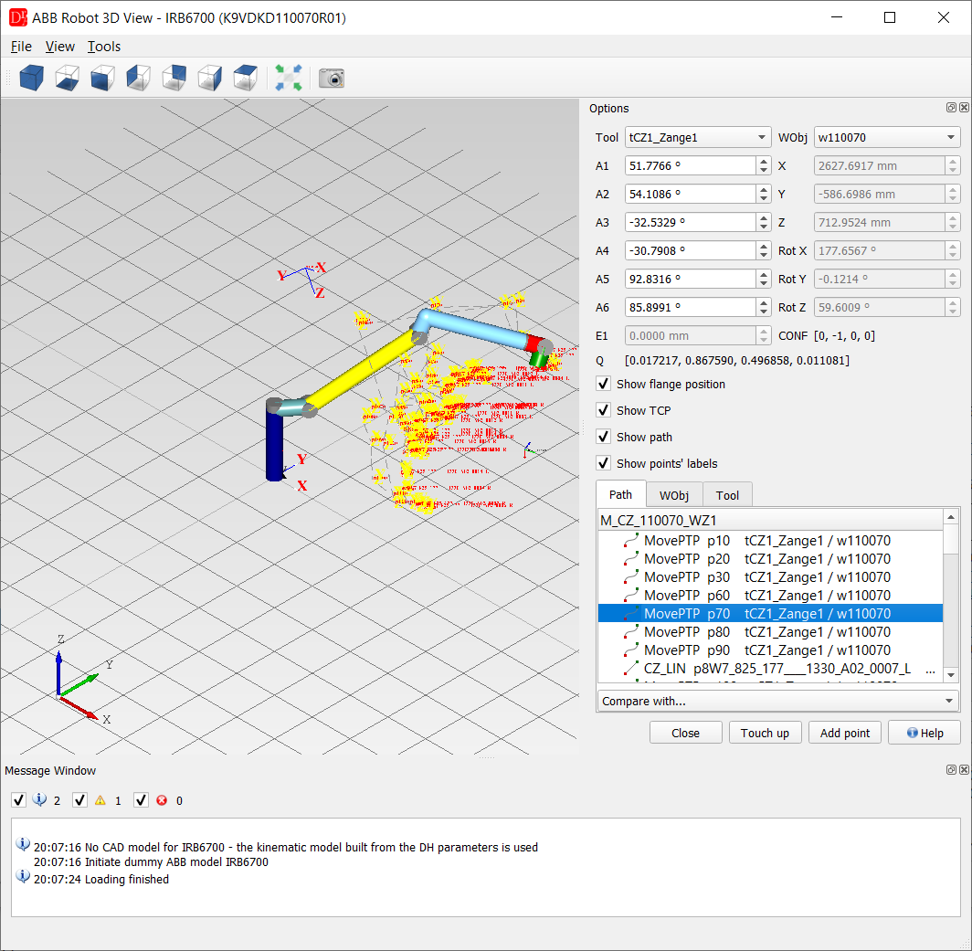
Window
- 3D view - robot model, path of the program, frames and TCP; views (axonometric, front, top ...), Fit in view and Grab the preview (export of the view to an image) in the toolbar,
- View menu - display mode (shaded / wire frame), grid on / off,
- Tools menu - add a cube or a sphere to the scene (e.g. to check a fence or an obstacle), grab the preview, Options (grid and colour settings),
- Message Window - information about the model, the kinematics and the points (errors, axis limits, unreachable positions).
- Tool / WObj - tool data and work object of the selected instruction,
- A1 .. A6, E1 - axis values; changing them moves the robot, X, Y, Z, Rot X/Y/Z, the quaternion Q and the configuration CONF are calculated,
- Show flange position, Show TCP, Show path, Show points' labels,
- Path - motion instructions of the module with the target, tool and work object,
- WObj - work objects of the module,
- Tool - tool data of the module,
- Compare with... - draws the path of another module from the same directory.
- Touch up - writes the current position of the robot to the selected point,
- Add point - adds a new motion with the current position after the selected point.
Touch up and Add point change the program in the editor (the file is saved as usual) and require the
ABB license. Paths generated off-line are not safe - test an off-line program before running the robot in
automatic mode.
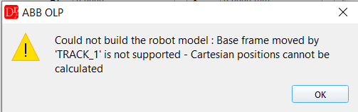
Only 6-axis robots are supported. A robot with a track or an external mechanical unit
(for example TRACK in MOC.cfg) is reported with Only 6 DOF ABB robots are supported.
Robot mounting: without a track the base frame of the robot must be the world frame
(base_frame_pos / base_frame_orient in MOC.cfg not set or 0) and gravity_alpha /
gravity_beta must be 0 (floor mounted). Otherwise no Cartesian positions are calculated and the robot is
not drawn - the message window shows the values.