
- Opening the editor
- Inserting a new motion
- Coordinates, axes and 3D preview
- Motion parameter bar
- Renaming a point
- Changing the motion type
- Joint points (E6AXIS) vs cartesian points (E6POS)
- What Apply writes, and where
- Safety options for global points
The KRC editor has a built-in point editor for the three basic motion types - PTP, LIN and CIRC. It edits the point itself (coordinates) and the inline form of the motion (type, velocity, approximation, tool, base), so a complete motion can be changed from one window without touching the raw fold text.
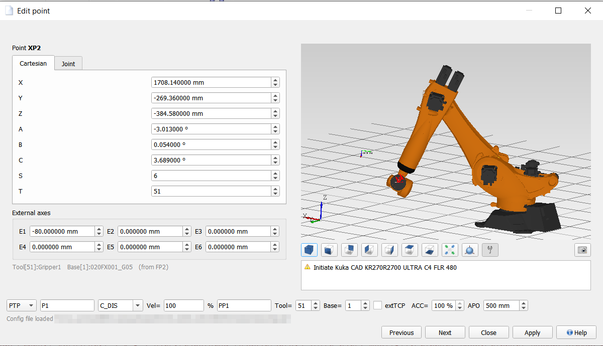
The window has four parts: the coordinates of the point on the left, in two tabs (Cartesian and Joint) with the external axes below them and the tool/base of the motion under those; the 3D preview on the right, with the view buttons and the message panel; the motion parameter bar along the bottom; and the path of the robot configuration the window is working with, right above the buttons.
The built-in editor is used for plain PTP/LIN/CIRC folds - those whose body follows
the standard five-line layout generated by the controller
($BWDSTART, PDAT_ACT/LDAT_ACT, FDAT_ACT,
BAS(...), motion line).
Technology points (spot welding, gluing, servo gun, ...) are not edited by it: they carry parameters the basic form knows nothing about, so rebuilding such a fold with it would destroy them. For those folds the parameter bar is switched off and the window says so - their parameters are edited through their own command form from the KRL Command Catalog, while the coordinates can still be edited normally in the upper part of the window.
Technology points (spot welding, gluing, servo gun, ...) are not edited by it: they carry parameters the basic form knows nothing about, so rebuilding such a fold with it would destroy them. For those folds the parameter bar is switched off and the window says so - their parameters are edited through their own command form from the KRL Command Catalog, while the coordinates can still be edited normally in the upper part of the window.
▲ Opening the editor
- double-click the motion fold in the program text, or
- use Edit point coordinates from the editor's right-click menu, or
- double-click the point in the point table.
▲ Inserting a new motion
Insert motion point (the robot toolbar) adds a new motion on the line of the cursor and opens this window on it. What lands in the program first is a complete, valid PTP fold, and next to it, in the program's .dat file, the three declarations every motion needs: the position (XP<n>), the frame (FP<n>) and the motion data (PP<n>).
The new motion is placed after the line of the cursor, but never inside another fold. If the cursor sits on a fold - which is the usual case, since a collapsed motion is a single line to click on - the new one goes after that fold's ;ENDFOLD, not between its header and its body. The only case that is refused is a fold with no ;ENDFOLD at all, because then the program's fold structure is already broken.
Before anything is inserted, the editor asks how the point is to be declared - XYZABC (E6POS) or JOINT (E6AXIS) - with two buttons of which only one can be active at a time. These are not two views of the same thing: the same TCP position can be reached in several arm configurations, so the axis form carries information the Cartesian one does not, which is exactly why HOME positions use it. The choice is remembered for the next insertion, but the question is always asked, because it decides what the point is - changing it later rewrites the whole declaration.
The new point starts from the neighbouring motion - the preceding one, or the following one when there is none before it - together with its tool and base. The frame comes along because Cartesian coordinates mean something only in a particular one: copying the numbers alone into a point with tool 0 and base 0 would silently place it somewhere else entirely. When the neighbour is stored in the other form than the one chosen, the values are converted through inverse or forward kinematics.
Without a neighbour - or when that conversion cannot be calculated - the point falls back to all coordinates 0, tool 0, base 0. The editor says which of the two happened: in the type dialog before the insertion, and again in a message afterwards. Velocity starts at 100 %. Everything else is set in this window and written by Apply.
The number <n> is the next free one, counted over the positions, frames and motion data of the program and of its global position files at once, so all three declarations of the new point share it. How the motion data declaration is named follows the convention of the file it lands in, read from the neighbouring motion: XP5 goes with PP5 in a file written by OrangeEdit and with PPP5 in a BMW archive. It is only a proposal: the name can be changed in the motion parameter bar, and if the new name is already taken, the same question appears as when renaming any other point (see Renaming a point). The proposed declarations are then dropped, because nothing refers to them any more.
Closing the window without a single Apply undoes the whole insertion: the motion
disappears from the program and the three declarations from the point table. A motion to a
point full of zeros, which nobody confirmed, has no business staying in a program.
Motions outside the three basic types - technology commands such as Swi_AdvSpot or SG_MOVE - are inserted from the KRL Command Catalog instead, which carries their own parameter forms.
▲ Coordinates, axes and 3D preview
Two tabs show the same position in both representations, kept synchronized:
- Cartesian - X, Y, Z, A, B, C plus S (status) and T (turn);
- Joint - A1 to A6, each with a slider limited to the axis software limits read from the robot's machine data.
External axes E1-E6 are shown once, below the tabs - they are the same for both representations. E1 takes part in the kinematic chain (linear unit); E2-E6 are carried through unchanged.
The 3D preview shows the robot in the edited position, with the tool coordinate system of the motion's tool and, optionally, the work envelope. It follows every value change immediately. If no CAD model is available for the configured robot type, a substitute kinematic model is used and the panel says so.
▲ Motion parameter bar
The bar along the bottom of the window (see the screenshot above) holds the parameters of the motion's inline form - the same fields the controller shows on the smartPAD:
- Motion type - PTP, LIN or CIRC;
- Point name - written without the leading X (typing P1 means the declaration XP1, the frame FP1, and so on);
- Auxiliary point - only for CIRC, which needs two points (an auxiliary one on the arc and the end point);
- Approximation - empty for an exact positioning move, or C_DIS (distance), C_ORI (orientation), C_VEL (velocity), C_PTP (axis-specific). The field is editable, so an unusual value already present in the file is kept as it is instead of being normalized away;
- Vel - velocity, in % for PTP and in m/s for LIN/CIRC. It is kept as text, exactly as written, so a value like 0.1 never comes back from the editor as 0.100000;
- motion data list name - the name of the PDAT/LDAT declaration. This field is read only: it follows the point name (see Renaming a point);
- Tool and Base numbers - their names from $config.dat are shown next to the tabs, exactly as the controller composes them for the fold header;
- extTCP - stationary tool (IPO_FRAME #TCP), i.e. the part is carried by the robot and the tool stands still;
- ACC (%) and APO (mm) - acceleration and approximation distance from the PDAT/LDAT declaration in the .dat file.
▲ Renaming a point
Typing a different point name is a full rename of the motion's target: the fold, the frame declaration and the motion data declaration all follow it.
The motion data list name is not edited directly - it keeps the relationship the fold already had, which differs between controllers and program generators:
| point / motion data before | after renaming P1 to P9 | why |
|---|---|---|
| P1 / PP1 | PP9 | motion data = prefix + point name |
| P1 / P1 | P9 | motion data = point name |
| HOME / DEFAULT | DEFAULT | a shared record - renaming one point must not detach the fold from data used by other motions |
If the new name belongs to a point that already exists in the program (or as a global position), the editor asks what that means:
- Yes - use the existing point's coordinates here. The motion now goes to the same place as the other one; the values shown in the window are discarded;
- No - keep the coordinates shown in the window and overwrite the existing point with them. This changes that position in every program that uses it;
- Cancel - nothing is changed.
▲ Changing the motion type
PTP uses a PDAT declaration, LIN and CIRC use LDAT - so switching the type also switches the motion data record. If the target declaration does not exist yet, it is created (and appended to the .dat file on the next save) with the default values the controller uses for a new point. Switching to CIRC additionally needs an auxiliary point; if the field is empty, a name derived from the end point is proposed so there is something to correct rather than an empty name in the generated fold.
The CIRC inline form could not be verified against real controller files - not a
single CIRC fold was available as a reference in the material used to reconstruct the fold
format. Its layout is derived from LIN by analogy, so the editor asks for confirmation
before generating one and the result is worth checking on the controller.
▲ Joint points (E6AXIS) vs cartesian points (E6POS)
A point is stored in the .dat file either as axis values (E6AXIS) or as cartesian coordinates (E6POS). The editor never changes that on its own: for a joint point the axis values A1-A6 are written back, for a cartesian point the X/Y/Z/A/B/C values are. When a joint point is open, the message panel says so explicitly.
This is not a formality. The same TCP pose can be reached with several different arm
configurations, so replacing axis values with a pose converted from the cartesian tab can
change the real path the robot takes to that point. Deciding to change the storage
form of a position is a job for the person standing at the real robot, not for the editor.
The cartesian tab remains fully usable for a joint point: a value typed there is converted to axis values through inverse kinematics, and those axis values are what ends up in the file.
▲ What Apply writes, and where
Apply commits the whole window in one go, in this order: first the motion parameters (which may rewrite the fold text), then the coordinates.
- the fold text in the .src file is rebuilt only if a parameter that is visible in it actually changed. Everything the bar does not edit is carried over unchanged: the controller version stamp (%R), the command catalog and variant markers, a collision-detection suffix, foreign lines inside the fold body (for example torque monitoring), the exact text of the closing ;ENDFOLD line, and the spacing style of the body;
- coordinates follow the usual rules: a local point is updated in memory and written when the program is saved; a global/HOME point is written to its shared .dat file immediately;
- ACC/APO/Vel are written into the PDAT/LDAT declaration, and Tool/Base/extTCP into the FDAT declaration. A value that did not actually change is not rewritten, so untouched declarations stay byte for byte as they were.
▲ Safety options for global points
Two options in Settings » KRC » Others, both enabled by default, protect positions that are shared by every program of a robot:
- Block assigning XYZABC coordinates to global JOINT HOME positions - HOME positions live in a global .dat file and are stored as axis values on purpose. With this option on, the editor refuses to overwrite them with values converted from the cartesian tab and explains why;
- Block changing point type (JOINT <-> XYZABC) for global points - changing the storage form of a global point rewrites its whole declaration and affects every program that refers to it, so the option is not offered for global points at all.
Robot mounting: only a robot standing in $WORLD ($ROBROOT = {0,0,0,0,0,0}) or a robot on
the E1 linear unit is supported; for another $ROBROOT the editor shows the reason instead of joint or Cartesian
values.
