
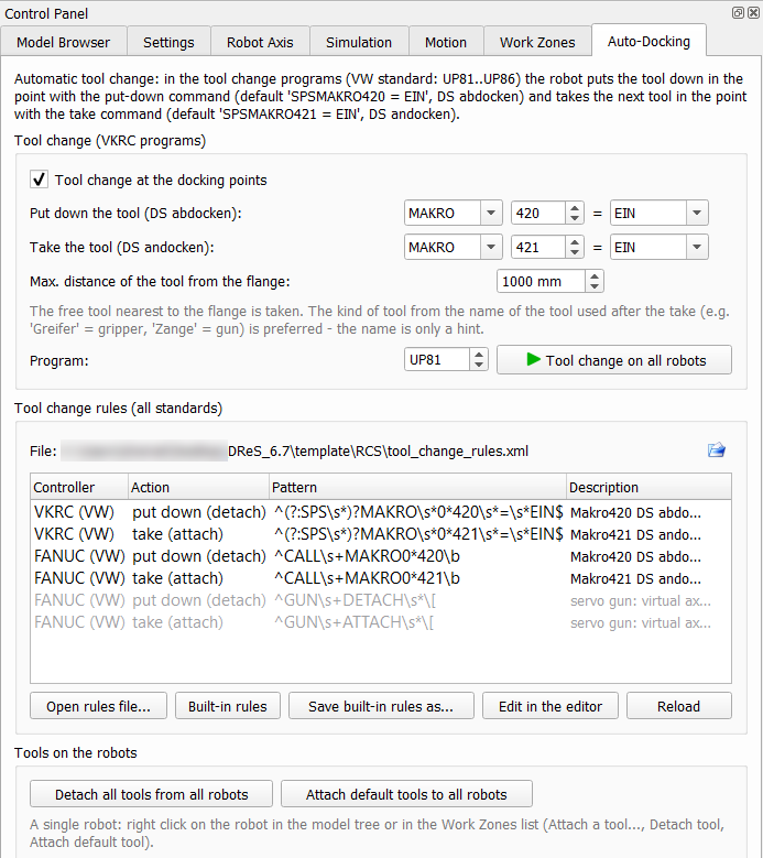
In the VW standard the tool change programs (UP81 ... UP86) put the tool down in the point with SPSMAKRO420 = EIN (DS abdocken) and take the next tool in the point with SPSMAKRO421 = EIN (DS andocken). The Auto-Docking repeats this in the simulation of VKRC programs. Simulation
 |
|
Every put-down and take is written to the console with the point, the station and the distance:
R_6600R01_G P20: tool '..._gre_11_...' taken from the station (MAKRO421 = EIN, DS andocken, 607 mm from the flange)
R_6550R01_G P23: tool take (MAKRO421 = EIN, DS andocken) - no free tool within 1000 mm of the flange (nearest Gripper: ..., 2848 mm)
The last message means that the tool expected by the program is not at the docking position in the layout – attach it by hand or increase the maximum distance.
The tools in the docking stations always stay opaque, also with transparent components.
Tool change rules (all standards)
The group Tool change rules extends the two commands above with rules from an XML file – for other standards and other controllers. A rule is a regular expression on the text of a program command and the action detach (the tool stays in the station) or attach (the robot takes the tool):
- VKRC – the title of the fold without the step number, e.g. SPSMAKRO420 = EIN, UP81 = M83, A17 = EIN,
- FANUC – the program line (LS, English) without the line number and without ';', e.g. CALL MAKRO420.
Built-in rules (VW standard): VKRC SPSMAKRO420 = EIN / SPSMAKRO421 = EIN, Fanuc CALL MAKRO420 / CALL MAKRO421; GUN DETACH / GUN ATTACH (Fanuc servo guns) are included but switched off, because they are also used outside the docking (e.g. GUN ATTACH at the start of programs).
| Button | Function |
| Open rules file... | uses the rules of an XML file (the file name is stored in the settings) |
| Built-in rules | back to the rules of the VW standard |
| Save built-in rules as... | template of the rules file to adapt to another standard |
| Edit in the editor | opens the rules file in the DReS editor |
| Reload | reads the file again after a change |
<Standard name="VW" controller="VKRC">
<Rule action="detach" pattern="^(?:SPS\s*)?MAKRO\s*0*420\s*=\s*EIN$" description="Makro420 DS abdocken"/>
<Rule action="attach" pattern="^(?:SPS\s*)?MAKRO\s*0*421\s*=\s*EIN$" description="Makro421 DS andocken"/>
</Standard>
<Standard name="VW" controller="FANUC">
<Rule action="detach" pattern="^CALL\s+MAKRO0*420\b" description="Makro420 DS abdocken"/>
<Rule action="detach" pattern="^GUN\s+DETACH\s*\[" enabled="false" description="servo gun"/>
</Standard>
</ToolChangeRules>
The table lists the rules in use; a grey row is a rule switched off with enabled="false" (it is read, but not used).
Creating your own rules
- Save built-in rules as... – save the template (e.g. tool_change_rules.xml next to the study) and answer Yes to Use the saved file as the tool change rules?
- Edit in the editor – change, add or remove rules; to use a switched off rule (e.g. GUN DETACH / GUN ATTACH when the servo guns are really docked with these commands) set enabled="true" or remove the attribute. Save the file.
- Reload – the table shows the new rules, the console the number of rules or the error with the line.
The installation contains the rules file template\RCS\tool_change_rules.xml (in the installation folder of DReS, the same rules as the built-in ones). It is used when no rules file is set yet. Another file is selected with Open rules file... or with the folder icon on the right of the file name (a long path is shortened in the middle, the tool tip shows the full path); the file name is stored in the settings of Robot Cell Simulator and used at the next start. Built-in rules switches back to the VW standard (the file is not changed). Copy the template before changing it – a new installation overwrites the files in template\RCS.
| Element / attribute | Meaning |
| <Standard name controller> | group of rules; name – free text (e.g. VW, BMW, Daimler), controller – VKRC or FANUC (ABB, YASKAWA, KRC are reserved for later versions). Several groups for the same controller are all used; the first matching rule (order in the file) decides. |
| action | required: detach – the tool is put down in the station, attach – the robot takes the nearest free tool |
| pattern | required: regular expression (Perl syntax, not case sensitive) on the command text described above; use ^ and $ to match the whole command, \s* for optional spaces, 0* for leading zeros. In XML write &, <, > instead of &, <, >. |
| enabled | optional: false switches the rule off (default true) |
| description | optional: text shown in the table and in the console messages of the tool change |
A rule file with an error (wrong regular expression, rule without action) is not used – the message names the line and the previous rules stay active. The commands above have priority over the rules. The rules are part of the work zone calculation (tool on the flange between detach and attach); a change of the rules calculates the zones again.