
What it does
Robot Cell Simulator Lite (Plugins → Robot Cell Simulator Lite) is the light version of Robot Cell Simulator. It draws the robot cell from the top, in 2D, without 3D models and without a 3D graphics card, and answers two questions in a few seconds:
- Where can the robots of the cell meet? – the reach of every robot and the floor area its TCP uses in all programs (Folgen and UPs) of its archive,
- Are the programs protected there? – areas used by two or more robots are yellow when all motions there are under an interlock, red when at least one robot moves there without an interlock.
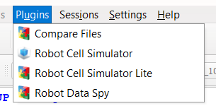
Robot Cell Simulator Lite in the Plugins menu
Only two inputs are needed: the cell study (positions of the robots) and the robot archives (programs, tools, bases, machine data). Robot Cell Simulator (basic)
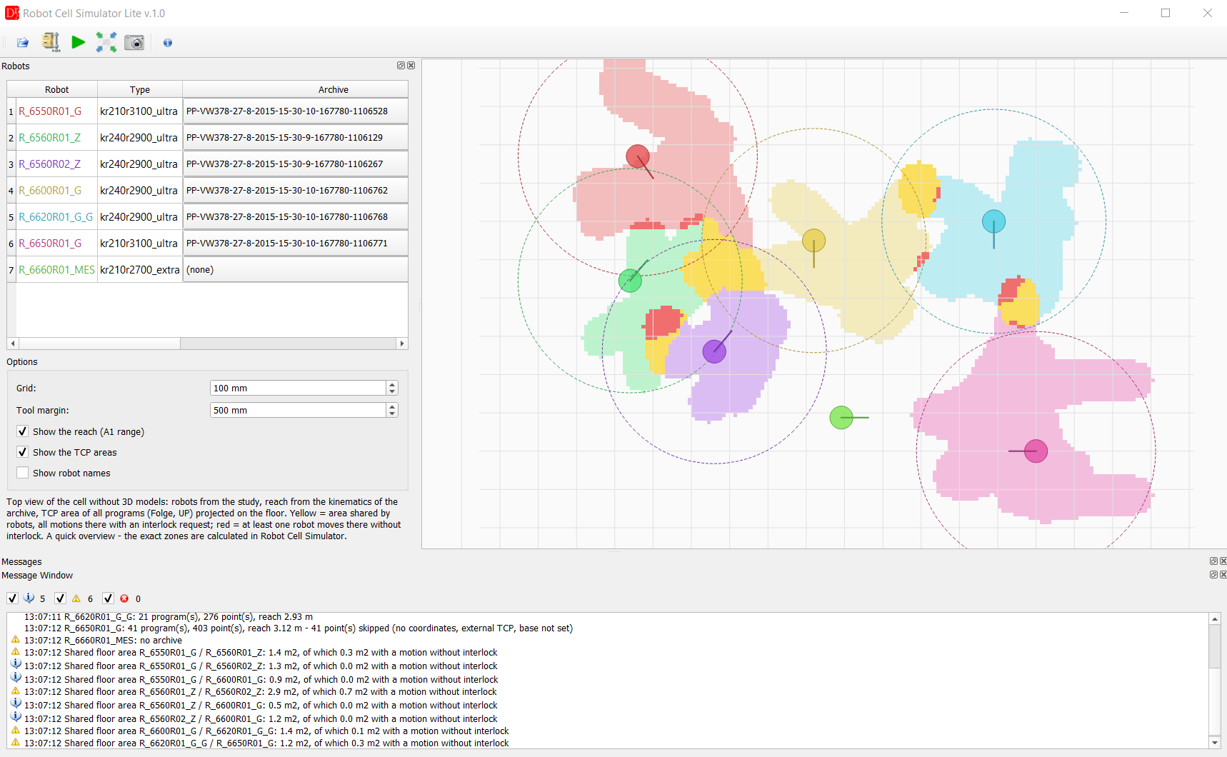
Top view: robots, reach, TCP areas and shared areas (yellow = with interlock, red = without interlock)
When to use it
- quick overview of a cell before the full simulation is prepared – at the line, on a laptop without a dedicated graphics card, also when the JT models of the cell are not available,
- first check after program changes: which robot pairs share an area and where an interlock may be missing,
- a picture of the cell layout with the working areas for a meeting or a report (Export image),
- choosing the robots and programs for the exact calculation in Work Zones.
Steps
- Open study – the cell study (*.psz) or the extracted StandaloneStudy_PsState.xml.
Only the robots are read (name, type, ExternalId, position and rotation in the cell); cost items, controller
cabinets, linear units and all other components are skipped, no JT file is loaded.
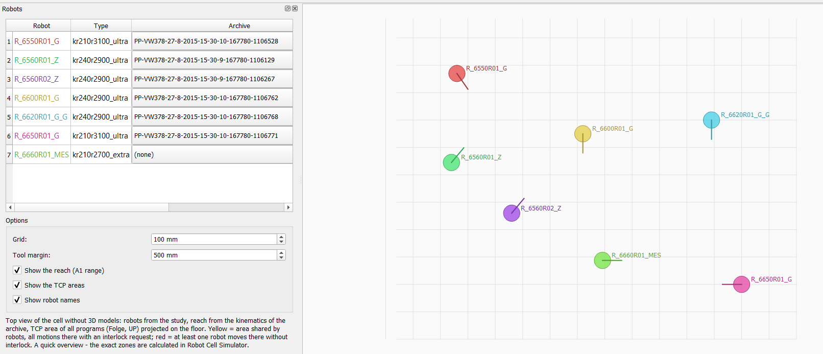 Robots of the study in the table and in the view (before Calculate)
 - Robot archives
 – the folder with the robot
archives. By default the folder set in Robot Cell Simulator is used; for a new study the sub folder archives
next to the study. The archives are assigned automatically (see Robots table).
– the folder with the robot
archives. By default the folder set in Robot Cell Simulator is used; for a new study the sub folder archives
next to the study. The archives are assigned automatically (see Robots table).
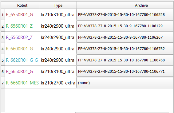 Archives assigned automatically, another archive chosen in the list
 - Calculate
 – reach, TCP area of all programs
and shared areas of every robot with an archive. The message window lists every robot (programs, points, reach)
and every robot pair with a shared area.
– reach, TCP area of all programs
and shared areas of every robot with an archive. The message window lists every robot (programs, points, reach)
and every robot pair with a shared area.
 Message window: robots and robot pairs with the shared floor area in m²
 - Export image
 – saves the current view as PNG.
Toolbar
| Button | Function |
 Open study Open study |
cell study *.psz (packed) or StandaloneStudy_PsState.xml (unpacked); the dialog opens in the folder of the last study |
| Robot archives |
folder with the robot archives (KRC folders with Folgen, UPs, $config.dat, $machine.dat); after the choice the archives are assigned again |
| Calculate |
reach and TCP areas of all robots, shared areas, summary in the message window |
 Fit all Fit all |
shows the whole cell in the middle of the view; the view is fitted again when the window is resized, until it is zoomed or moved by hand |
| Export image | saves the view as PNG |
 Documentation Documentation | opens this page |
Every button has a tooltip. Mouse wheel = zoom at the cursor, drag = move the view.
Robots table
| Column | Content |
| Robot | name of the robot in the study, in the color of the robot in the view; the tooltip shows the ExternalId and the position in the cell |
| Type | robot type from the study |
| Archive | assigned archive: sub folder named by the ExternalId of the robot, otherwise a folder with the robot number in its name (R_6550R01_G → ...6550r01...). The list allows to choose another archive or (none); the tooltip shows how the archive was assigned. |
| Programs, Points | number of Folgen / UPs and of points used in the calculation |
| Reach [m] | reach of the flange (see What is shown) |
| Note | result of the calculation: skipped points, no VKRC programs in the archive, ... |
Options
| Option | Meaning |
| Grid | size of the floor cells of the TCP areas (default 100 mm); a smaller grid gives finer edges and a longer calculation |
| Tool margin | the TCP path is widened by this radius (default 500 mm) – it stands for the tool and the wrist around the TCP, see How the areas are calculated |
| Show the reach (A1 range) | reach circle (or sector) of every robot |
| Show the TCP areas | TCP areas and shared areas |
| Show robot names | names next to the robots |
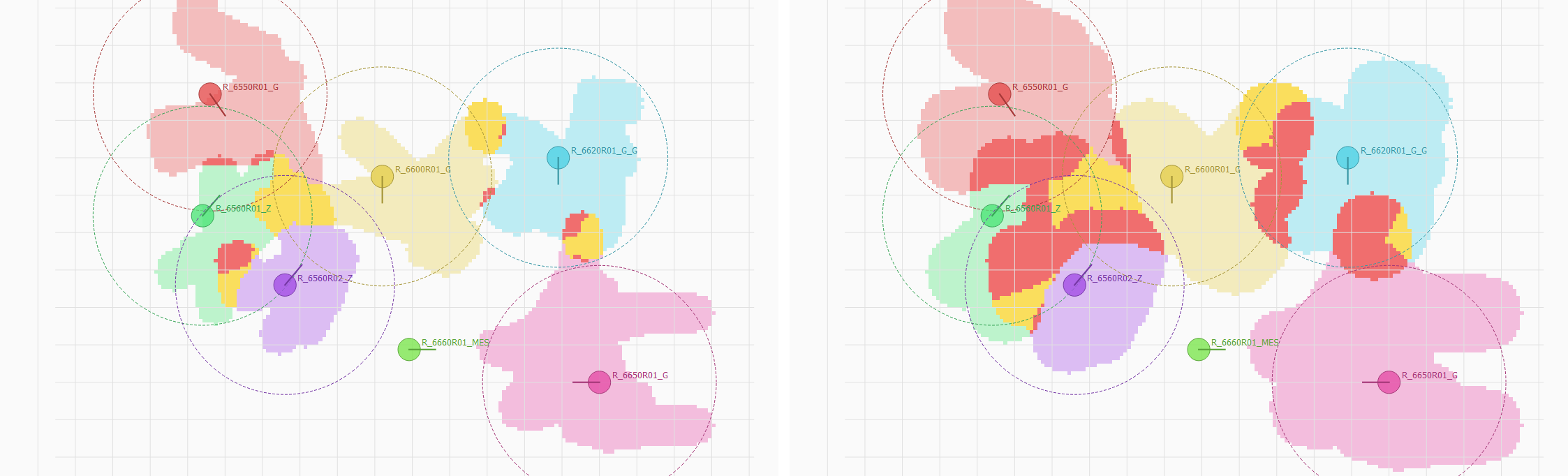
The same cell with tool margin 500 mm (left) and 1000 mm (right)
What is shown
- Robot – circle at the base and a line in the direction of axis 1 (A1 = 0).
- Reach (dashed) – largest horizontal distance of the flange from axis 1, calculated with the kinematics and the software limits of A2 / A3 of the archive; a sector when the range of A1 is less than 360°. The tool is not added to the reach.
- TCP area – floor cells passed by the TCP of the programs, widened by the tool margin; each robot has its own color.
- Shared areas – yellow where two or more robots move and all motions there are under an interlock (request activated until the release), red where at least one robot moves there without interlock.
- The message window lists for every robot pair the shared floor area in m² and the part with a motion without interlock.
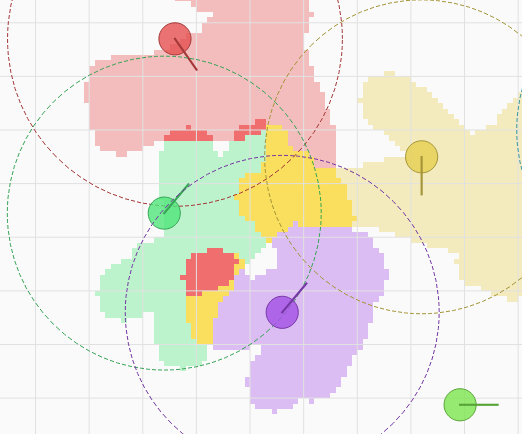
Detail: shared area of two robots, yellow part with interlock, red part without interlock
How the areas are calculated
Robot Cell Simulator Lite does not use any 3D model – neither the robot nor the tool. The areas come only from the programs and the machine data of the archive:
- All points of all Folgen and UPs are read (positions in their base, base data from $config.dat) and converted to the cell with the position of the robot from the study.
- A programmed point is the position of the TCP of the tool used in the point. The area therefore follows the tool tip (e.g. the electrodes of a gun, the center of a gripper), not the flange.
- The points are connected with straight lines in the program order and projected to the floor (heights are not used).
- Every floor cell passed by the TCP is widened by the tool margin (circle with the given radius). The margin is the only representation of the tool body and the wrist – the real size of the tool mounted on axis 6 is not known. For large grippers or guns increase the margin (e.g. 800–1000 mm).
- The arm between the base and the wrist (A2 / A3 links) is not part of the area. Where the arm reaches over another robot, Lite shows no shared area.
- The interlock state of every motion comes from the program logic (same check as in Archive Diff - interlocks): a motion is under an interlock when the request was activated before it and is not yet released.
Advantages over Robot Cell Simulator
- No graphics card, no 3D models – runs on any office laptop or a PC at the line; the JT files of the cell and the component library are not needed.
- Seconds instead of minutes – the study is read without loading any part, the calculation of a whole cell is usually done in seconds (Robot Cell Simulator: loading the cell and the work zones take minutes).
- Small memory – no scene with tens of thousands of parts.
- Clear 2D picture – the whole cell at one glance, with the reach of every robot; easy to export and to show in a meeting.
- Nothing to set up – no system root, no tools to attach, no motion parameters: study and archives are enough.
- Only the basic license – the Simulation and Work Zones modules are not needed.
Limits compared with Robot Cell Simulator
- Top view only (no heights): two robots working one above the other are shown as shared.
- No robot body and no tool model: the area may be too small where the arm or a large tool reaches far from the TCP, and too large where a small tool works with a large margin.
- Straight lines between the points (no motion planner) – a PTP motion can leave the line, the approximation of the corners is not taken into account.
- No motion, no simulation: no run of the programs, no cycle times, no Touch up, no tool change.
- No automatic correction: interlocks are not inserted or checked point by point (Insert interlocks and Check interlocks are functions of Robot Cell Simulator).
- Points with external TCP and points in a base that is not set are skipped (count in the column Note). Robots on a linear unit (E1) are drawn without the E1 offset.
- Only VKRC archives (VW standard).
Use Lite for the overview and to find the robot pairs to look at. Before programs are changed or an
area is declared free, check it with the work zones of Robot Cell Simulator (robot links,
real tools, motion planner) and with Check interlocks.
Lite and Robot Cell Simulator
| Robot Cell Simulator Lite | Robot Cell Simulator | |
| View | 2D from the top | 3D cell with all components |
| Data | robots of the study, robot archives | study, JT models, robot archives |
| Graphics card | not needed | dedicated graphics card recommended |
| Time to the result | seconds | minutes (loading the cell, work zones) |
| Robot body | not used (TCP only) | 3D models of the links |
| Tool on axis 6 | only as the tool margin around the TCP | 3D model of the attached tool (option) |
| Path | straight lines between the points | motion planner (PTP, LIN, CIRC, approximation) |
| Heights | no | yes (voxels) |
| Interlocks | shared areas yellow / red | zone matrix, path in interlock colors, check and insert interlocks |
| Simulation, cycle times, Touch up | no | yes |
| License | Robot Cell Simulator (basic) | basic + Simulation / Work Zones modules |