▲ Point editor
The point editor edits one point of the job in degrees, in pulses and in Cartesian coordinates, and shows the robot in 3D. It is opened by:- a double-click on the point name in the text,
- Edit point C..... in the context menu of the viewer,
- Point editor C..... in the context menu of the point table.
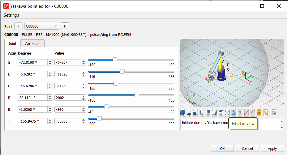
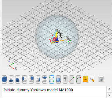
Point editor with the 3D preview and the work envelope of an MA1900.
The information line shows the point, its type, the control group, the robot model of the
XML file with the model name of the controller, and where the pulses per degree come from.
With the arrows next to the point name all points of the job can be walked through; if the
point was changed, the editor asks whether to apply the change first.
Joint tab
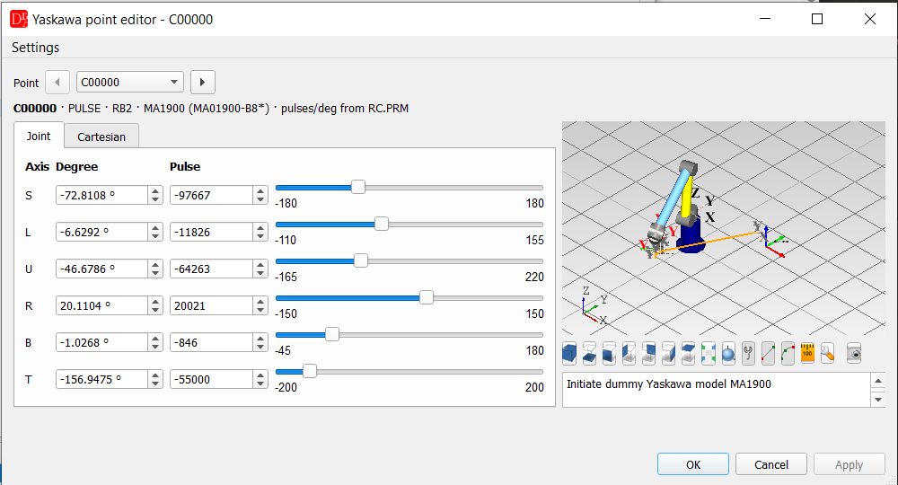
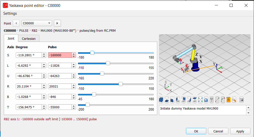
Enter in a field only confirms the value - the editor is closed with OK
(apply and close), Apply (apply and stay) or Cancel (asks before discarding a change).
Cartesian tab
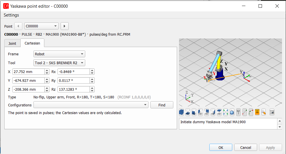
- Frame - Robot or any user frame of the robot from UFRAME.CND,
- Tool - any tool of TOOL.CND; by default the tool of the point,
- X, Y, Z, Rx, Ry, Rz - TCP of the point in this frame and tool. Changing a value moves the robot there (inverse kinematics, starting from the current axis values, so the configuration of the robot stays the same); if the position cannot be reached the values return and the reason is shown,
- Type - the configuration of the robot (see below),
- Configurations / Find - all axis solutions for the same TCP within the axis ranges; selecting one moves the robot to it.
Configuration (RCONF)
The configuration is shown as in ///RCONF l,m,n,o,p,q of a RECTAN job:| l | 0 Flip (B ≥ 0), 1 No-flip (B < 0) |
| m | 0 Upper arm, 1 Lower arm |
| n | 0 Front, 1 Rear (wrist before / behind the S axis) |
| o, p, q | R, T, S < 180° (0) or ≥ 180° (1) |
For a RECTAN point the axis values are found for the RCONF of the job; if the resulting configuration differs from ///RCONF, the editor says so. RECTAN jobs (Cartesian points in the job file) need the controller option Relative Job - most jobs are taught in pulses.
What Apply writes
- PULSE points are saved in pulses - the Cartesian values are only calculated,
- RECTAN points are saved as X, Y, Z, Rx, Ry, Rz in their own frame (///POSTYPE, ///USER) and tool (///TOOL), whatever frame is selected for display,
- only the declaration line of the point is changed - the header lines of the job stay as they are. The job is marked as modified and saved with Ctrl+S.
3D preview
The preview is switched on in the menu Settings → Show robot 3D preview of the point editor; the 3D scene is created when the editor is opened, so after switching it on the editor has to be opened again (as in the point editors of ABB and Fanuc).The robot is drawn as a simplified model built from the geometry of the XML file - pedestal, motor on every axis, links between the axes, flange - in the robot coordinates of the controller. It follows every change of the axis values, the sliders and the Cartesian values.
| Button | Function |
| views | axonometric, bottom, front, left, back, right, top |
| fit all | whole scene in view; the mouse wheel zooms, the mouse moves and rotates the view |
| work envelope | transparent sphere with the reach of the robot around the S axis |
| TCP | arrows of the TCP (flange × tool selected in the Cartesian tab) with the tool name |
| points | TCP of all robot points of the job (same control group) in the order of the instructions, joined by a line; the edited point is highlighted, points at the same place share one label |
| user frames | user frames of the robot with their names; the frame of the Cartesian tab is drawn bigger |
| calibration position | moves the robot to the calibration position; the position is set with the button next to it |
| capture | saves the picture of the scene (PNG, JPG, BMP, PGM) |
▲ Kinematics
The geometry of the robots is in the file yaskawa/YaskawaGenericKinematics.xml (setting Yaskawa Generic Kinematics). It describes 102 Motoman models - AR, GP, HC, MA, MH, MPK, MPL, SIA, UP ... - including robots with an offset wrist, palletizers with a parallel link and 7-axis robots. For every model it contains:- the axes with a point on every rotation axis and its positive direction at the zero position, the axis ranges, and the flange,
- the height of the robot coordinate system above the mounting surface,
- payload, reach, repeatability and mass where known, and the reach calculated from the geometry,
- the combined L/U range of robots where the U range depends on L,
- verified="true" for models checked against the data of a real controller.
The kinematics of the MA1900 was checked on a DX100 backup: the origins of the user frames
taught in pulses (UFRAME.CND) are reproduced to 0.001 mm.
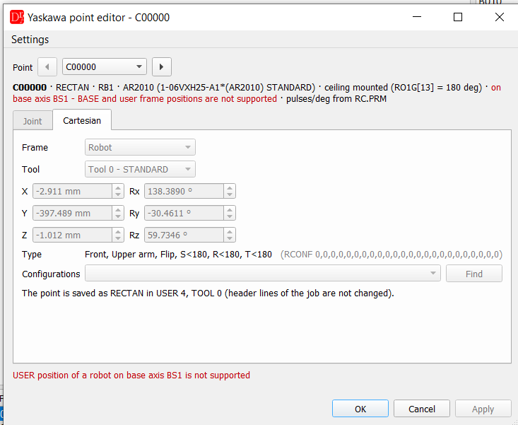
Ceiling mounted robots: the installation angle is read from RO.PRM. A robot hanging upside down
(180°) is taken into account in the axis ↔ Cartesian conversion and in the 3D preview (the robot hangs,
the grid lies on the mounting surface above it). Checked on a YRC1000 with an AR2010 on a gantry: the ROBOT
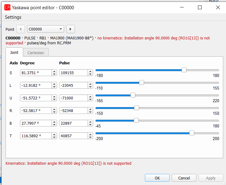
positions of the controller are reproduced to 0.001 mm and 0.0001°. Other installation angles are not
supported yet - there is no kinematics then (only axis values, no Cartesian values and no 3D preview) and the
info line says why. For a robot on a base axis (gantry) only the ROBOT frame is offered; BASE and USER
positions are reported as not supported.
Robot on a gantry (YRC1000, ceiling mounted AR2010 on the base axis BS1) - a point stored in USER 4: