
The Yaskawa OLP plugin (menu Yaskawa » Plugins » Yaskawa OLP) shows the JBI job opened in the Yaskawa viewer in a 3D environment. There are no CAD models of the Yaskawa robots - the robot is drawn as a dummy model from YaskawaGenericKinematics.xml (see Kinematics) with the pulses per degree of the controller. Everything is drawn in the robot coordinates (ROBOT) of the controller, the floor lies on the mounting surface of the robot. A ceiling mounted robot (installation angle 180° in RO.PRM) is drawn hanging with the grid at the ceiling. For a robot on a base axis (gantry) the path is drawn in the robot coordinates; points stored in BASE or USER coordinates need the position of the base axis, which is not modelled - they are not drawn and the message window lists them:
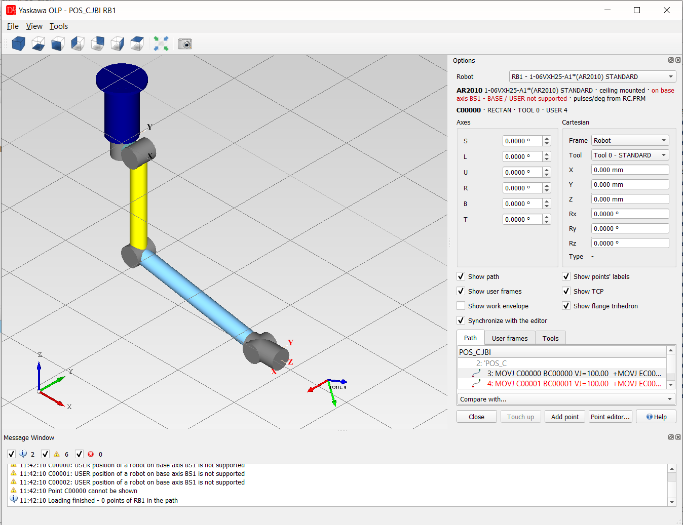
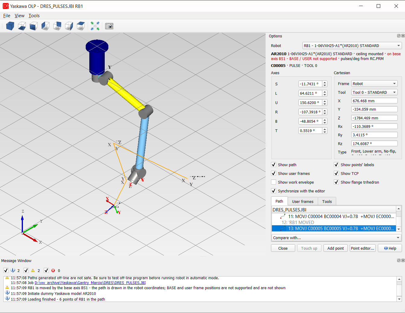
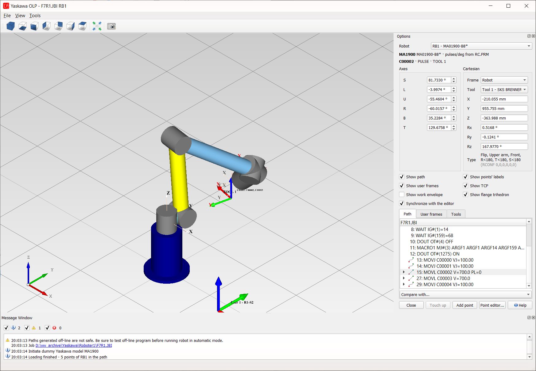
Window
- 3D view - robot model, path of the program, frames and TCP; views (axonometric, front, top ...), Fit in view and Grab the preview (export of the view to an image) in the toolbar,
- View menu - display mode (shaded / wire frame), grid on / off,
- Tools menu - add a cube or a sphere to the scene (e.g. to check a fence or an obstacle), grab the preview, Options (grid and colour settings),
- Message Window - information about the model, the kinematics and the points (errors, axis limits, unreachable positions).
- Robot - control group of the job (RB1, RB2 ...); the path contains the robot points of this group,
- S, L, U, R, B, T (and E for 7-axis robots) - axis values in degrees within the range of the model; values outside the range of the model or outside the soft limits of the controller are marked red,
- Frame / Tool - frame (robot or a user frame of UFRAME.CND) and tool (TOOL.CND) of the Cartesian values X, Y, Z, Rx, Ry, Rz; Type is the configuration of the robot (RCONF),
- Show path, Show points' labels, Show user frames, Show TCP, Show work envelope, Show flange trihedron,
- Synchronize with the editor - the selected motion follows the cursor in the editor and the other way round,
- Path - every motion instruction with its line number; the instructions after a motion are its children, comments are grey. Red lines have a point which cannot be shown, grey lines have no point of the selected robot. A double click shows the line in the editor,
- User frames - frames of UFRAME.CND, each can be hidden; the selected one is drawn bigger,
- Tools - tools of TOOL.CND with their weight; selecting a tool sets the TCP,
- Compare with... - draws the path of another job of the same controller in blue.
- Touch up - writes the current axis values to the point of the selected motion (PULSE points in pulses, RECTAN points in their own frame and tool),
- Add point - new PULSE point C..... (next free number) at the current axis values with the tool of the Tool combo and its motion line (MOVJ or MOVL, editable) after the selected motion. The point is declared in //POS with the ///TOOL, ///POSTYPE and ///PULSE lines it needs and ///NPOS is updated. Only for the robot of ///GROUP1 of the job,
- Point editor... - opens the point editor of the point.
Touch up and Add point change the program in the editor (the file is saved as usual) and require the
Yaskawa license. Paths generated off-line are not safe - test an off-line program before running the robot in
automatic mode.
See also 3D Modelling for the CAD repository of robot models.