
 DReS Robot Cell Simulator - Tools on the Robots: Attach, Change, Tool Change UP81 on All Robots (YouTube, English)
Tools on the robots
When a cell is opened, the tools placed on the flanges in the study are attached to the robots. The column Attached to of the Model Browser and the list in the Work Zones tab show the current tool of every robot. Tools are changed by hand with the context menu of a robot or a tool:
- Attach to robot... – attaches the selected tool to a chosen robot,
- Detach, Detach tool, Detach fixtures – leave the tool (fixtures) at the current place,
- Attach default tool – restores the tool from the study.
Components that can be a tool (grippers, guns, docking systems, components mounted in the study) have a hammer icon in the Model Browser: gray = free, orange = attached to a robot, crossed out in red = changed in this session compared to the study. The default tool is the tool mounted on the robot in the study.
The dialog Attach sets the robot, Tool or Add fixture (e.g. a part in the gripper) and the mounting position on the flange (X Y Z, A B C). Buttons fill in the position:
- Position from the study – the mounting position saved in the study,
- Keep the position in the cell – the component stays exactly where it is in the view,
- Model origin on the flange – only when the origin of the tool model lies on the flange,
- Same as the current tool – the position of the previous tool.
Check the result by moving A6. When the study contains a complete mounting chain (tool changer → adapter → tool), the whole chain is attached automatically. The robot menu in the Work Zones list offers the same functions: Attach a tool... / Change the tool..., Add a fixture on the flange..., Detach tool, Show the tool in the model tree, Attach default tool.
Detaching all tools and attaching the default tools of all robots is in the Auto-Docking tab.
Robot Axis tab
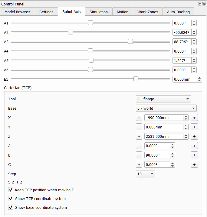 |
The tab moves the current robot (selected in the Model Browser). The sliders and spin boxes set the axes A1–A6 and the linear unit E1 within the limits from the machine data. The robot follows immediately in the 3D view. Keep TCP position when moving E1 compensates the 7th axis: the TCP stays in place while the robot moves along the linear unit. Show TCP coordinate system and Show base coordinate system draw the frames in the 3D view. |
Cartesian jog
The group Cartesian (TCP) shows the TCP position in the selected Tool and Base (tool and base data from $config.dat of the robot archive). The buttons − / + move the TCP by the Step in X, Y, Z or rotate it around A, B, C; a value can also be typed directly. The status S and T of the current position is displayed below.
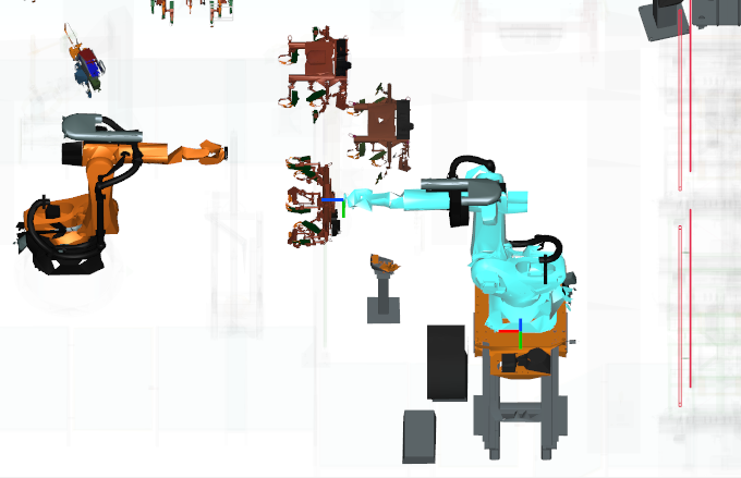
The current position can be written to a program point with Touch up.